

Kyle Shepherd
Resonant Ultrasonic Spectrometer
Project Overview
After my internship at Oak Ridge National Laboratory, I wanted to bring Resonant Ultrasonic Spectroscopy experimental capabilities to Rice. A Resonant Ultrasonic Spectrometer (RUS) is a device that can non-destructively measure the elastic constants of a material sample. The basic operating principal is the material is excited across a sweep of known frequencies, and the excitation magnitude of the sample is measured. The peaks of the excitation magnitudes are the "resonant" frequencies of the material. With these measured peaks and known material geometry, the elastic constants of the material can be back-calculated.
I chose to pursue this project because the construction of a RUS device seemed feasible, I have contacts at ORNL who built and tested their own device, and they referenced me to a good paper describing the construction process. "A versatile Lock-In digital Amplifier (LIdA): the case of mechanical resonances" by D Bessas and E Brück. https://doi.org/10.1088/1361-6404/aa6606. In addition, this project would expand my experimental skill sets, and would provide unique non-destructive testing capabilities to Rice University.
The current status of the RUS system is I have all of the needed parts, written
the necessary code, and I have successfully tested each individual component
except for the Analog-to-Digital Converter (ADC). However, assembling all of
the components together has not been successful, and I have identified the problem
to be excess noise in the circuitry components which is preventing the components from working
properly. I will need to reach out to the electric engineering department for
help with the circuit design to eliminate the noise problems. I suspect I need guidance on
component placement and decoupling capacitor placement.
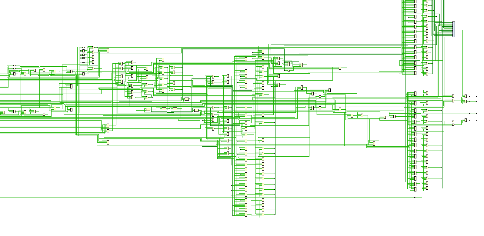
The current circuit design is shown below. Some connections have not been drawn and shown yet.
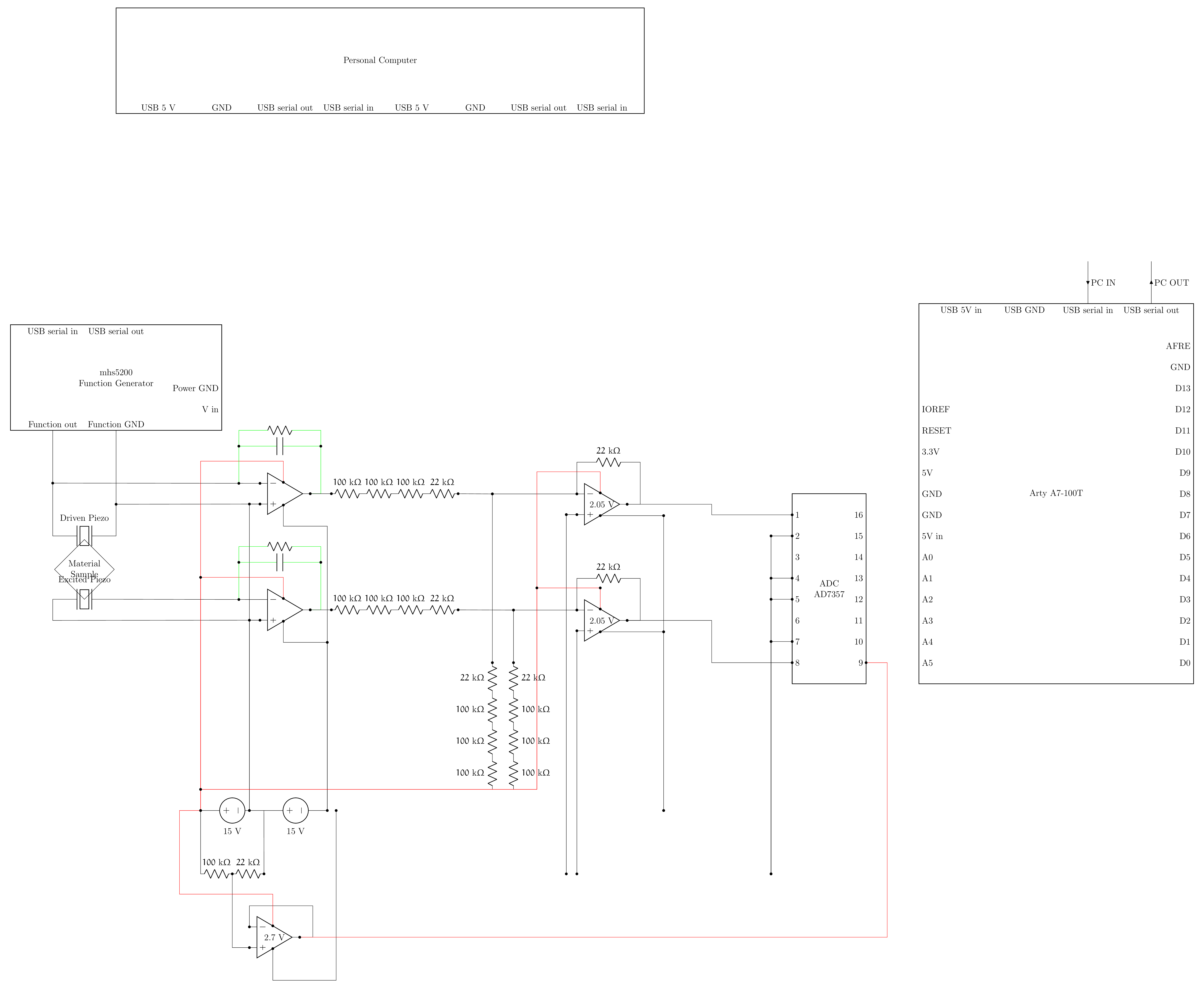 Click to download the .tex code that generated the electrical diagram
Project Construction Details
To begin this project, I read through the paper "A versatile Lock-In digital
Amplifier (LIdA): the case of mechanical resonances" by D Bessas and E Brück
https://doi.org/10.1088/1361-6404/aa6606.
which describes the RUS construction process. However, direct replication of this
paper was not possible due to some materials not being available and due to the
device interfacing being performed in LabView, a language I am not familiar with.
Therefore, I had to determine suitable substitutions for the materials used in
the paper. To determine these substitutions, I had to learn different areas in
electrical engineering.
My goal was to make "good enough" substitutions in order to have a working prototype,
and then use the knowledge I gained to reach out to electrical engineering
students and professors to improve the design if needed.
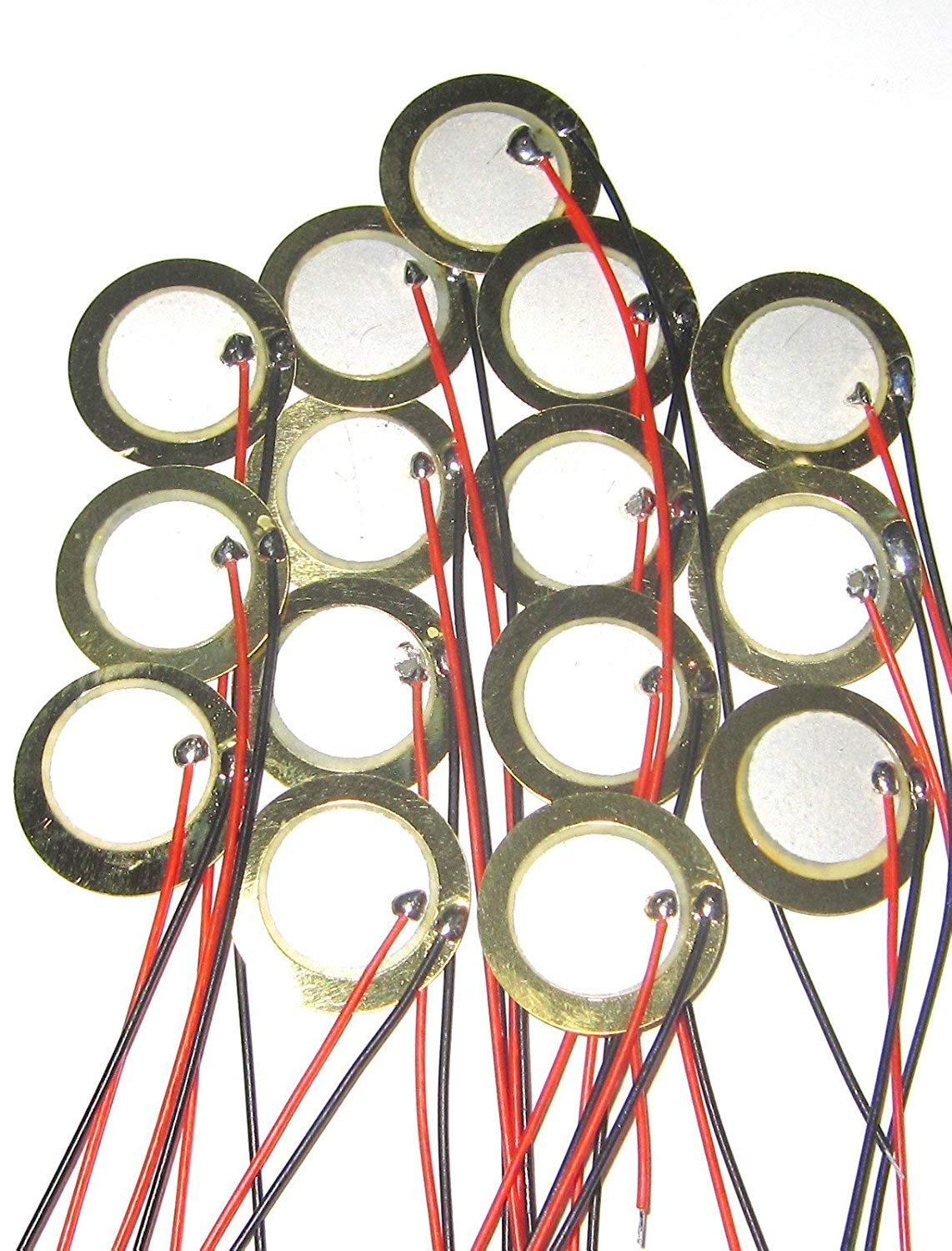
The first substitution I had to make was for the piezo sensor. The link provided in the paper for the piezo source was a dead link, and I could not easily find a piezo with the given dimensions of 0.4 mm thickness and 10 mm diameter online. I opted to get simple 20mm disk piezo sensors, thinking the larger area should accommodate slightly larger material samples.
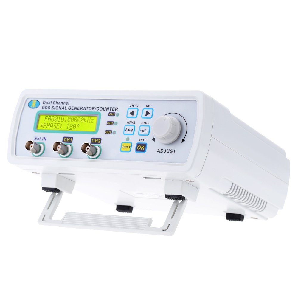
The second substitution I had to make was the electrical signal generator.
After some research, the MHS-5200A Series dual-channel DDS signal generator
was within my price range and functionality for the RUS prototype.
The spec sheet can be downloaded here.
In addition, the serial communication protocol has been reversed engineered,
so it is possible to write computer code to control the MHS-5200A over wire.
This allows the RUS system to automatically sweep across a range of frequencies
without needing the user to manually set frequencies.
Leveraging my familiarity with Python, I was able to use the PySerial package
to perform serial communication with the MHS-5200A. Example code causing the
MHS-5200A to continually increase the output frequency from 10,000 Hz is shown below.
 1 import serial
 2 import numpy
 3 # Serial configuration.
 4 cfg = dict()
 5 # Serial Basics
 6 cfg["port"] = "COM7"
 7 cfg["baudrate"] = 57600
 8 # Flow Control
 9 cfg["xonxoff"] = False
10 cfg["rtscts"] = False
11 cfg["dsrdtr"] = False
12 # Timeouts.
13 cfg["timeout"] = 0.5
14 cfg["write_timeout"] = 0.5
15 # Open the serial port.
16 porting = serial.Serial(**cfg)
17 # Flush input and output buffers.
18 porting.flushInput()
19 porting.flushOutput()
20 # Create the message string.
21 # The mhs5200 takes in frequency values in centiHertz, 1/100 of a Hz.
22 # This loop with cause the mhs5200 to step from 10,000 Hz to 900,000 Hz, 10 Hz at a time
23 # it increases as fast as the serial communication allows.
24 freq=numpy.arange(1000000,90000000,1000)
25 for k in freq:
26     msg="s1f"+str(k)
27     cmd_str = ":{}\r\n".format(msg)
28     # Send the message out the serial bus.
29     porting.write(cmd_str.encode())
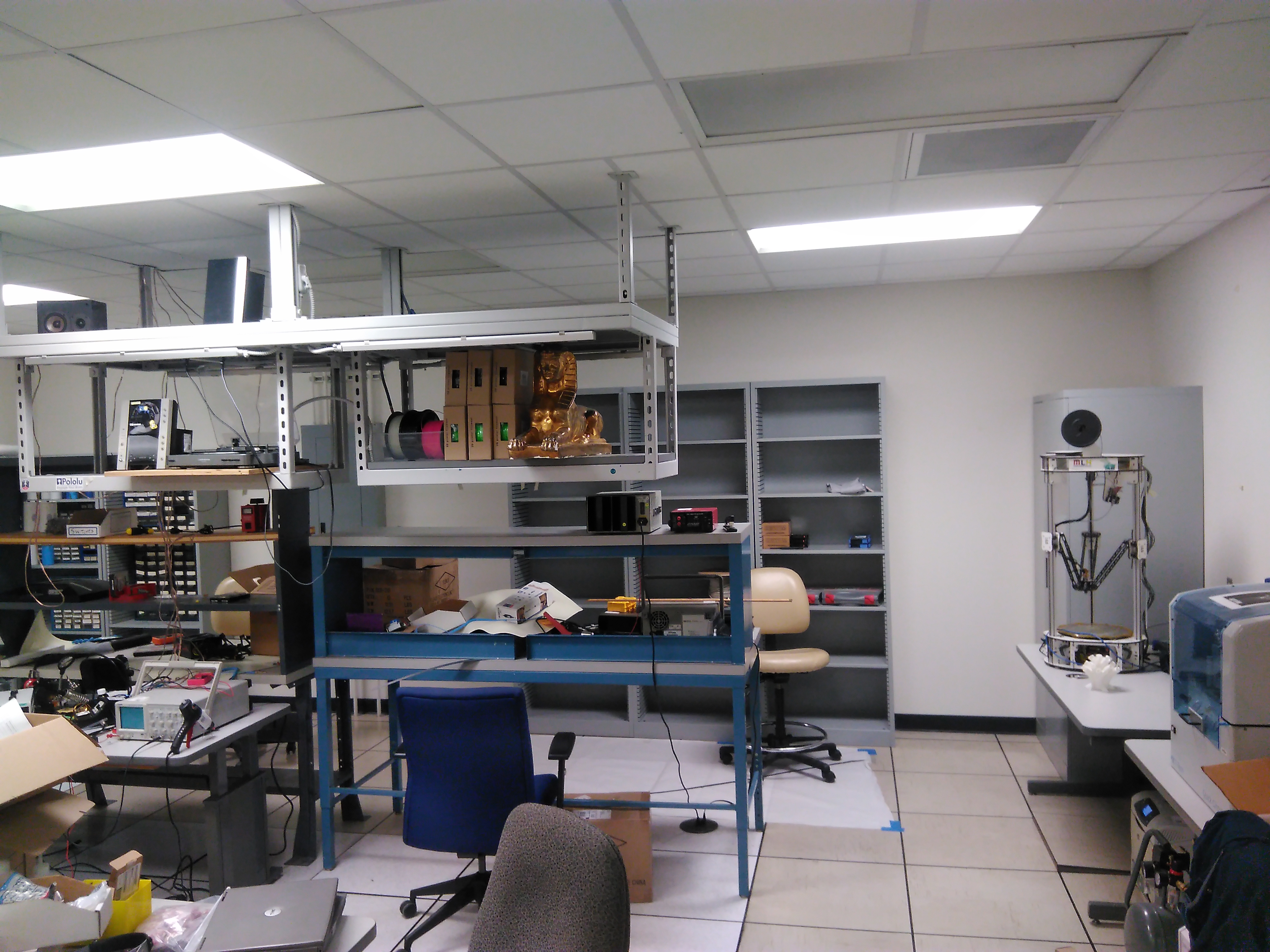
After obtaining the piezo sensors and the signal generator, I needed a way to test these components. Specifically, I wanted to determine if the signal generator was creating a clean signal and being successfully controlled by the PC serial connection. I needed access to an oscilloscope to measure the output of the signal generator. By reaching out to Rice's IEEE student chapter, they were able to help me out and they granted me access to the Ethernest, a small makerspace on Rice campus with some electrical hardware. Using their oscilloscope, I confirmed the successful wired control of the signal generator.
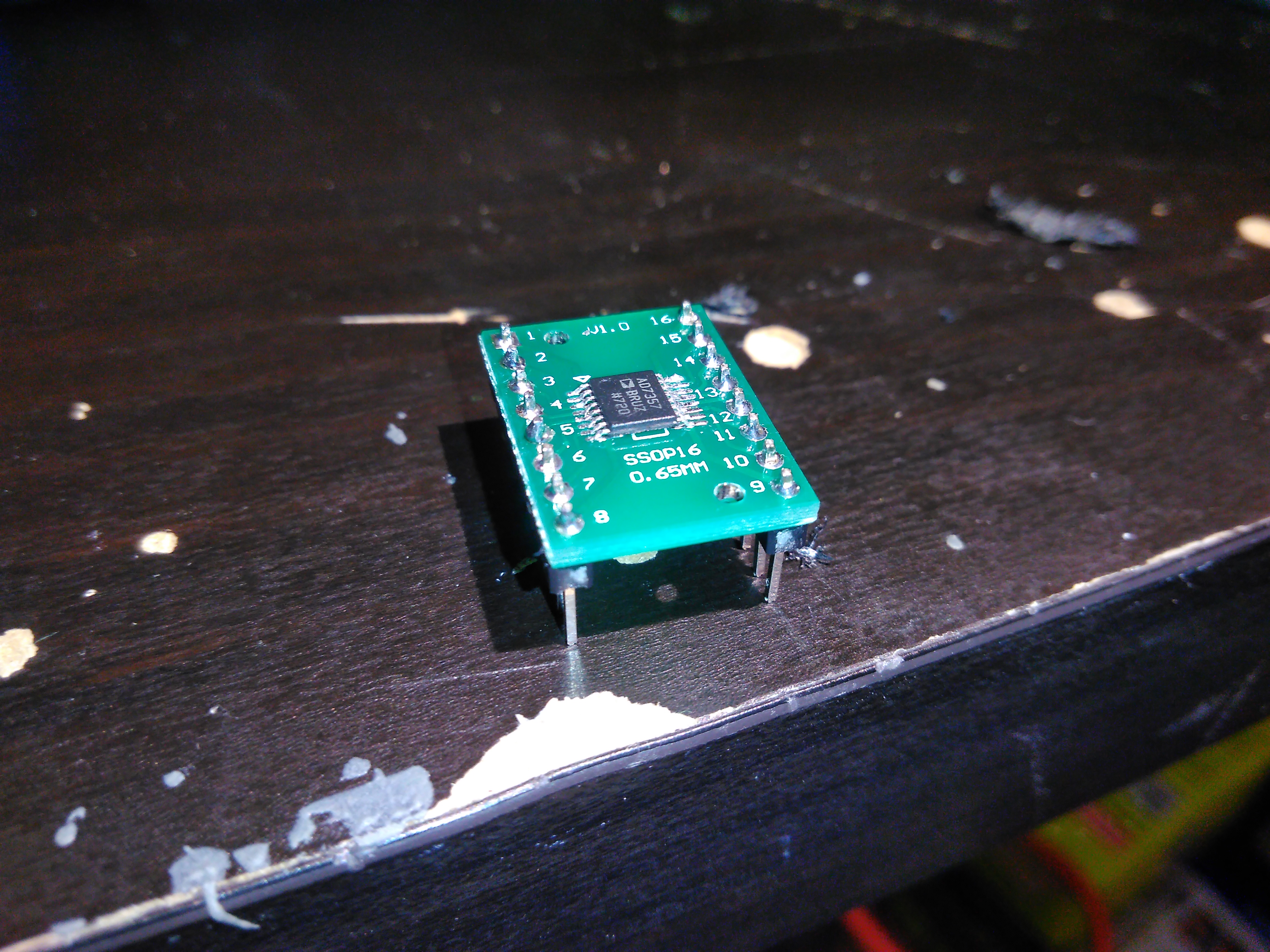
The third substitution I had to make was the Analog-to-Digital Converter (ADC). This piece of hardware converts an analog voltage signal to a digital value with some defined bit resolution. The referenced paper successfully used a 14-bit AD7357 ADC, so I requested a sample of my own from Analog Devices. From my experience at Oak Ridge National Laboratory, frequencies up to 1 MHZ need to be measured, so the ADC collecting samples at 4.2 MSPS allows me to capture signals up to 2.1 MHz. I chose to get the individual component and not the evaluation board so I would not be locked in the Analog Devices ecosystem of parts. To interface the ADC with the rest of the system, I needed to solder the ADC to a breakout board, and solder on header pins. I had some concern that the breakout board and pins were not arranged properly for minimizing noise and cross talk and other symptoms of high frequency systems, but I was willing to accept some noise for a system that would be easier to debug. If the noise needs to be removed, a proper circuit board could be designed later.
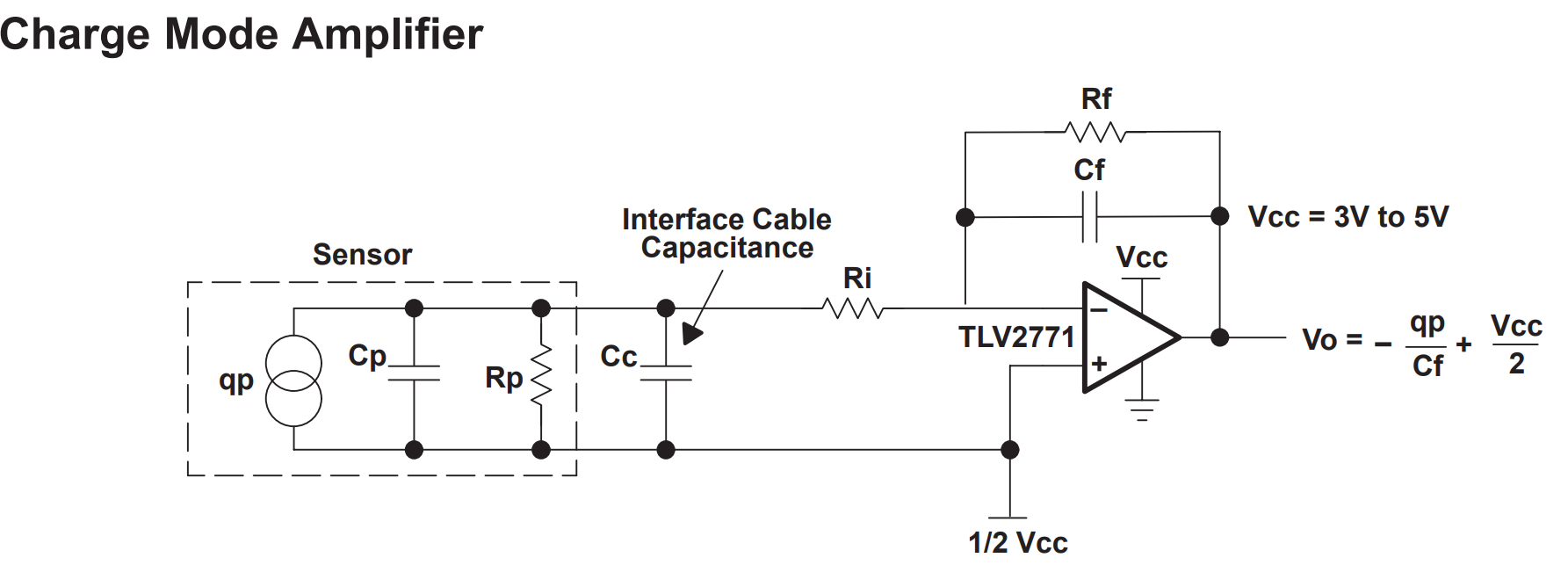
The fourth substition I had to make was to condition the electrical signals coming from the piezo sensors. Trying to read a voltage directly from the piezo sensor will not be successful for a few reasons. One, the voltage of the piezo cannot be easily controlled and could spike too high and fry electronics. Two, piezo sensors are charge devices, as in the greater the signal, the greater the electric charge in the piezo. This mostly correlates with voltage, but the act of measuring the piezo with the ADC will drain the very small amount of charge and give a different reading. The solution to these problems is to use op-amps. These devices are powered from an external power supply, and can output a voltage proportional to the sensor voltage without draining the charge in the sensor. For piezo sensors, it is recommended to use a "charge amplifier" scheme to condition the signal, as seen to the side.
One criteria for the op-amps is to make sure they have a fast enough "slew rate".
This is a measure of how fast the voltage in a op-amp can change, and a fast
slew rate is needed to measure the high frequency piezo signals. The LM833 op-amp
was the first op-amp I found that met my needed criteria.
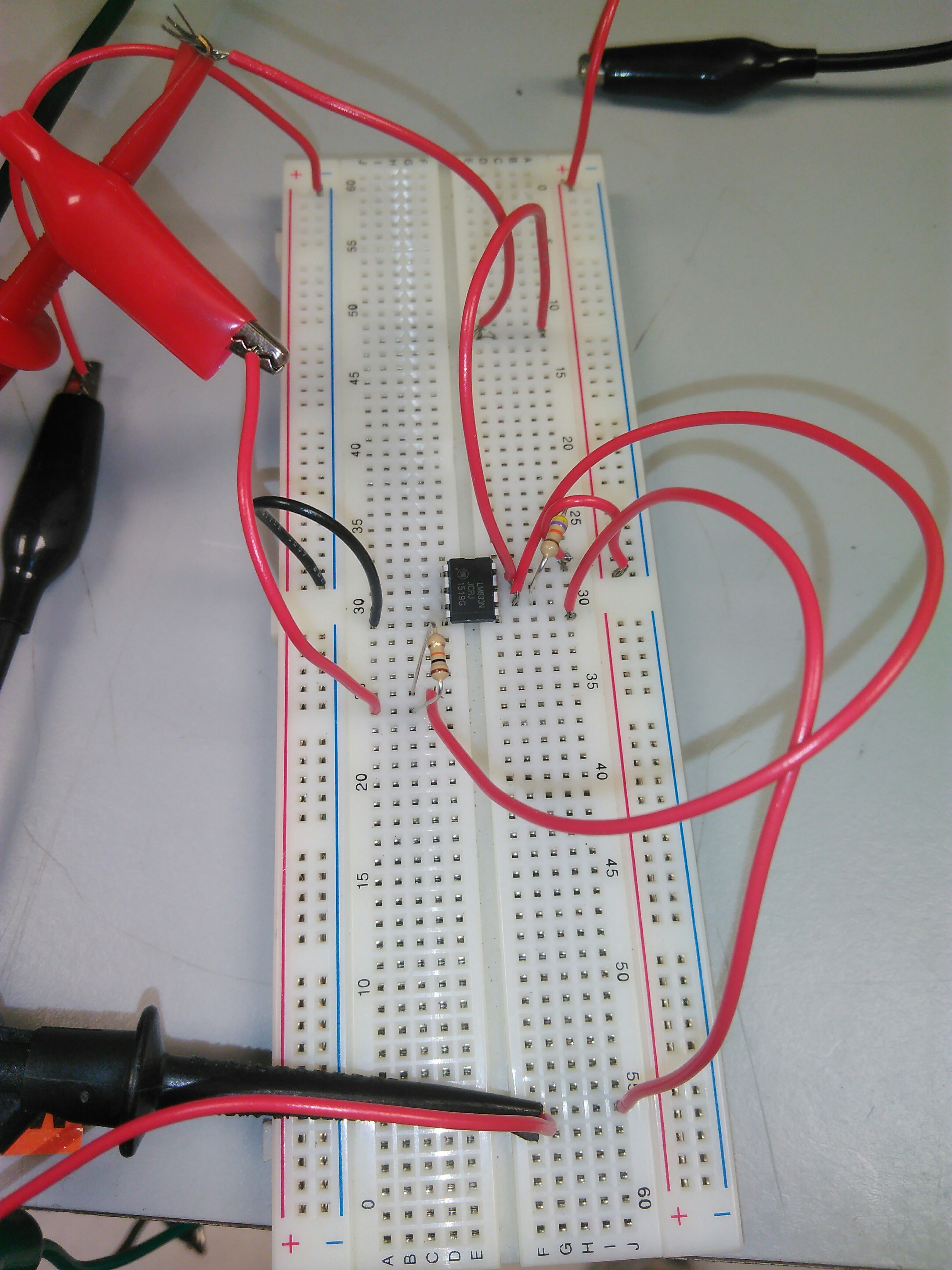
Getting the op-amp to work correctly for me was difficult. However, my problems
with the op-amps were solved when I correctly used a dual rail power supply.
A dual rail power supply has positive and negative voltages, because the electrical
ground of the system is set to the middle of the power supply output. Two separate
15V power supplies were successful in powering the op-amps.
The fifth substitution I had to make was the Field Programmable Gate Array (FPGA).
The FPGA serves as the brains of the RUS system. A FPGA is a device that can be
programmed, but it is programmed using a Hardware Description Language (HDL) to write
logic gates in the FPGA, instead using a language like C++ or Python to
write a sequence of CPU instructions to a normal computer. FPGAs are used when
computations are relatively simple, and the computations need to be performed
in parallel and performed fast.
FPGAs are ideal for data acquisition purposes because they can process very fast streams
of data.
In my case I just needed some device to quickly poll the ADC for voltage values,
and transmit the values to my PC for further data analysis.
I looked into using a traditional microcontroller like an Arduino,
but they were not acceptable for my purposes due to low clock speeds, needing
multiple clock cycles in serial to measure and store data, and imperfect control over
instruction interrupts that could disrupt the timing of the data collection.
Therefore, I had to use a FPGA.
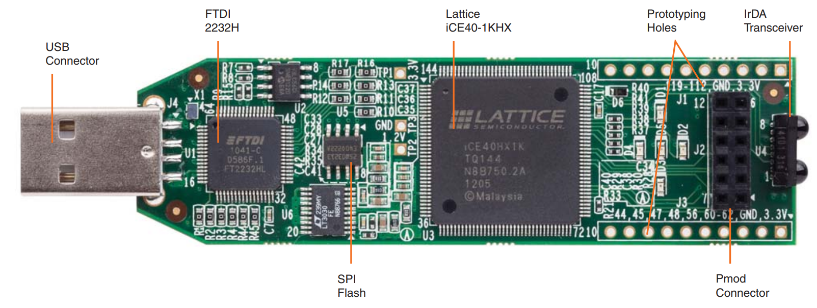
To learn how to use a FPGA, I obtained an ICEstick Evaluation Board with a iCE40HX1K FPGA. I chose this board because there are multiple tutorials for it online, and it was inexpensive. However, it does not have the specs I need for the RUS prototype system because it does not have a fast enough built-in clock and does not have enough on-board storage to hold the data while it is being sent to my PC. My goal was to learn FPGA programming on this cheap board, and later order a bigger, better FPGA with the specs I need. I could also write and debug the HDL code for the RUS using the small FPGA, and then simply recompile the HDL code for the larger FPGA.
After looking at some tutorials online, I learned the syntax of VHLD, a specific Hardware Description Language, and performed some LED blinking examples and successfully uploaded the code to the FPGA. After the LED blinking example, I implemented a Universal Asynchronous Receiver/Transmitter (UART) circuit in the FPGA, and was able to successfully send it data from my PC using a PySerial script. I could command the FPGA to blink an LED a certain number of times. The code for this example is shown below. However, my learning technique of repeatedly uploading code to the FPGA to debug and test the code exceeded the data write limits of the device, and I bricked it.
  1 -- ----------------------------
  2 --    iCEstick Serial In
  3 -- ----------------------------
  4 -- Created By:  Kyle Shepherd
  5
  6 --This code performs LED blinking tasks depending on the UART serial data
  7 --recieved from the computer
  8 --REDled1 and REDled2 blink out the binary representation of the number that the FPGA recieved
  9 --REDled3 turns on during the serial read process
 10 --REDled4 blinks the number of times equal to the number recieved over serial
 11 --The green LED indicates the last bit in the REDled1 and REDled2 blinking sequence
 12
 13 --libraries to understand numbers
 14 library ieee;
 15 use ieee.std_logic_1164.all;
 16 use ieee.std_logic_unsigned.all;
 17 USE ieee.numeric_std.ALL;
 18
 19 --defining inputs and outputs
 20 entity Blink is
 21     port(
 22             led         : out    std_logic; --green LED
 23             REDled1         : out    std_logic;
 24             REDled2         : out    std_logic;
 25             REDled3         : out    std_logic;
 26             REDled4         : out    std_logic;
 27             clk         : in    std_logic; --FPGA clock signal
 28             serialIn      : in    std_logic; --UART serial data from computer
 29             serialOut      : out    std_logic --UART serial data to computer
 30          );
 31 end Blink;
 32
 33 -- defines variables
 34 architecture Behavior of Blink is
 35     --states for reading and writing data. Used to handle start and stop bits
 36     type ReadState is (listening,reading,stopbit);
 37     signal    Rstate     :   ReadState   :=  reading;
 38     type WriteState is (StartData,SendData,StopData);
 39     signal    Wstate     :   WriteState   :=  StartData;
 40
 41     signal    flash     :   integer range 0 to 511 := 0; --count for blinking REDled4
 42     signal    DataInClock :   integer range 0 to 12000000; --count for clocking serial in processes
 43     signal    DataOutClock :   integer range 0 to 12000000; --count for clocking serial out processes
 44     signal    Mid :   integer range 0 to 32; --count for finding middle of start bit
 45     signal    WaitCount : integer range 0 to 32; --count for sampling the middle of each serial in bit
 46     signal    BitCount : natural range 0 to 9 := 0; --count for counting the number of recieved bits
 47     signal    BitShow : natural range 0 to 7 := 0; --count for blinking REDled1 and REDled2
 48     signal    Data : std_logic_vector(7 downto 0) := "10001010"; --vector for storing the recieved byte over UART
 49     signal    BitOut : natural range 0 to 7 := 0; --count for counting the number of sent bits
 50     --Hard coded defined value for the UART serial out to send to the computer, for debugging purposes
 51     signal    OutData : std_logic_vector(7 downto 0) := "10001010";
 52     --constants for UART serial data protocol
 53     constant ClockSpeed : integer := 12000000;
 54     constant Baud : integer := 1000000;
 55     constant Sample : integer := 6;
 56
 57 begin
 58     process(clk) --if clk changes, do the stuff below
 59     begin
 60         if (rising_edge(clk)) then --do stuff when clock signal goes positive
 61
 62           --UART serial out code block
 63           if (DataOutClock < ClockSpeed/Baud) then
 64             DataOutClock <= DataOutClock + 1; --clock cycle counter
 65           else
 66             DataOutClock <= 1;
 67             --only sends out data if the last command recieved is 24, or 00011000
 68             if (to_integer(unsigned(Data)) = 24) and (Rstate = listening) then
 69               case Wstate is
 70                 --sends start bit
 71                 when StartData =>
 72                   serialOut <= '0';
 73                   BitOut <= 0;
 74                   Wstate <= SendData; --changes state
 75
 76                 --sends data
 77                 when SendData =>
 78                   serialOut <= OutData(BitOut);
 79                   if (BitOut < 7) then
 80                     BitOut <= BitOut+1;--keeps track of which bits have been sent
 81                   else
 82                     BitOut <= 0;
 83                     Wstate <= StopData;
 84                   end if;
 85
 86                 --sends stop bit
 87                 when StopData =>
 88                   serialOut <= '1';
 89                   Wstate <= StartData;
 90               end case;
 91
 92             --holds serial line high when no data is being sent
 93             else
 94               serialOut <= '1';
 95               Wstate <= StartData;
 96             end if;
 97           end if;
 98
 99           --UART serial in code block
100           if (DataInClock < (ClockSpeed/Baud)/Sample) then
101             DataInClock <= DataInClock + 1;
102           else
103             DataInClock <= 1;
104
105             case Rstate is
106               --listening for a start bit
107               when listening =>
108                 REDled3 <= '0';
109                 BitCount <= 0;
110                 WaitCount <= 0;
111                 if (serialIn = '0') then
112                   Mid <= Mid + 1; --if the line is brought low, start counting
113                 end if;
114                 if (serialIn = '1') then
115                   Mid <= 0; --if the line is brought high early, ignore signal
116                 end if;
117                 if (Mid >= (Sample)/2) then
118                   Mid <= 0; --if the line is brought low long enough, start reading data
119                   Rstate <= reading;
120                 end if;
121
122               --reading UART data
123               when reading =>
124                 REDled3 <= '1'; --turns LED on
125                 if (WaitCount >= Sample-1) then
126                   Data(BitCount) <= serialIn; --Saves sampled bit to the Data vector
127                   WaitCount <= 0;
128                   BitCount <= BitCount + 1;
129                 else
130                   WaitCount <= WaitCount + 1;
131                 end if;
132                 if (BitCount >= 8) then
133                   BitCount <= 0;
134                   Rstate <= stopbit;--change state to read the stop bit
135                 end if;
136
137               when stopbit =>
138                 WaitCount <= WaitCount + 1;
139                 BitCount <= 0;
140                 --wait the entire duration of the stop bit, then go to the listening state
141                 if (WaitCount >= Sample-1) then
142                   WaitCount <= 0;
143                   flash <= 0;
144                   Rstate <= listening;
145                 end if;
146               end case;
147           end if;
148
149           --LED blink code block
150           if (count < ClockSpeed/3) then --block triggers every 1/3 of a second
151             count <= count + 1;
152           else
153             --flashes REDled4 on a number of times equal to data
154             if (flash < 2*to_integer(unsigned(Data))) then
155               REDled4 <= not REDled4;
156               flash <= flash + 1;
157             end if;
158             --visual indicator of last bit in the sequential LED binary display
159             if (BitShow >= 7) then
160               led <= '1';
161               BitShow <= 0;
162             else
163               led <= '0';
164               BitShow <= BitShow + 1;
165             end if;
166
167             --turns on REDled1 or REDled2 depending on the binary value in Data, as the
168             --BitShow value increments
169             REDled1 <= Data(BitShow);
170             REDled2 <= not Data(BitShow);
171             count <= 0;
172           end if;
173         end if;
174     end process;
175 end Behavior;
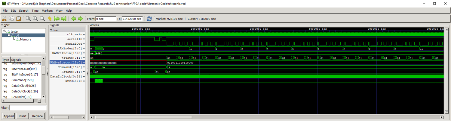
This hardware failure forced me to learn how to perform simulations of my code and write proper
testbench code. Unfortunately, freely available simulation software for VHDL is not easily found,
so to simulate my code I had to translate it from VHDL to Verilog.
This actually works out well since Verilog has a stronger community and code base behind it.
Once the code was translated, I used Icarus Verilog to perform the simulations.
While debugging my code using the simulator, I obtained a new FPGA, the
Arty A7-100T: Artix-7 FPGA Development Board. This FPGA has the specs I need,
and it should not fall prey to the write limits I reached on the smaller board.
I have successfully performed UART serial communication at 5 million baud with
this board, which can offload the collected and stored ADC data at each
frequency point in ~0.2 seconds.
The current version of the Verilog code for collecting the frequency data for the
RUS system is shown below.
  1 // ----------------------------
  2 //    FPGA Ultrasonic Vibration Data Collection
  3 // ----------------------------
  4 // Created By:  Kyle Shepherd
  5 // Date:  Feb 1, 2019
  6
  7 // defines the module
  8 module FPGAultrasonic(
  9   input clk, // FPGA 100 mhz clock signal
 10   input serialIn, // serial signal from computer
 11   input ADCdatain, // signal from ADC
 12   output reg serialOut, // serial signal to computer
 13   output reg led, // diagnostic LED
 14   output reg ADCsignalCS); // signal to control the ADC
 15
 16 // define parameters, constants
 17   // constants to control UART serial communcation
 18 parameter ClockSpeed = 50000000;
 19 parameter BaudRate = 921600;
 20 parameter SampleRate = 9;
 21   // constants to control RAM data storage
 22 parameter ADDR_WIDTH = 18;
 23 parameter DATA_WIDTH = 16;
 24 parameter DEPTH = 2**ADDR_WIDTH;
 25
 26 // declare integers
 27 reg [0:26] DataInClock = 0; // controls timing of reading serial UART data
 28 reg [0:26] DataOutClock = 0; // controls timing of writing serial UART data
 29
 30 reg [0:4] BitReadCount = 0; // counts number of bits read from serial UART data
 31 reg [0:4] BitWriteCount = 0; // counts number of bits written to serial UART data
 32 reg [0:4] TrackCount = 0; // counts the number of cycles for the ADC to track and hold the next voltage
 33
 34 reg [0:26] Sync = 0; // count for syncing clock for serial UART reading
 35 reg [0:26] SerialSampleCount = 0; // count for serial UART reading
 36
 37 reg [0:17] BitWriteIndex = 0;
 38 reg [0:17] BitSampleIndex = 0;
 39
 40 // declare states
 41 reg [0:1] Rstate = 0; // serial UART read state
 42 reg [0:1] Wstate = 0; // serial UART write state
 43 reg [0:2] ADCstate = 0; // ADC communication state
 44
 45 // declare data vectors
 46 reg [7:0] UARTbuffer = 8'b00000000; // vector for storing read serial UART data
 47 reg [15:0] Command = 0; // vector storing last command from computer, sent over serial
 48
 49 // handle memory access
 50 reg [ADDR_WIDTH-1:0] RAMindex = 0; // RAM data index, data picker
 51 reg ReadWrite = 0; // defines if the RAM is in read or write state
 52 reg [DATA_WIDTH-1:0] RAMvaluein = 0; // data to write to RAM
 53 wire [DATA_WIDTH-1:0] RAMvalueout = 0; // data read from RAM
 54
 55 // imports the RAM module
 56 SRAM #(
 57   //send in parameters
 58   .ADDR_WIDTH(ADDR_WIDTH),
 59   .DATA_WIDTH(DATA_WIDTH),
 60   .DEPTH(DEPTH))
 61   Memory(
 62   .clk (clk),
 63   .addr (RAMindex),
 64   .write (ReadWrite),
 65   .i_data (RAMvaluein),
 66   .o_data (RAMvalueout)
 67 );
 68
 69 // additional clocks
 70 reg clk_main = 0; // clock running main logic, is synthesized from the FPGA clock
 71
 72 // Wires
 73
 74 // clk_wiz_0 ADCclock (
 75 //   .clk_out1 (ADCclk),
 76 //   .reset (),
 77 //   .locked (),
 78 //   .clk_in1 (clk)
 79 // );
 80
 81 // clock synthesis
 82
 83 // cuts clock frequency in half
 84 always @(posedge clk) begin
 85   clk_main <= !clk_main;
 86 end
 87
 88 // defines what happens each clock cycle
 89 // the FPGA does its stuff during the rising clock edge
 90 // the ADC it talks to does it stuff on the falling edge
 91 // https://www.analog.com/media/en/technical-documentation/data-sheets/ad7357.pdf
 92 always @(posedge clk_main) begin
 93
 94   // Writing serial UART data logic
 95   if (DataOutClock < ClockSpeed/BaudRate) begin
 96     DataOutClock <= DataOutClock + 1;
 97   end else begin // sends out data at the Baud Rate
 98     DataOutClock <= 1;
 99
100     if (Command == 24) begin
101       case (Wstate)
102         // start UART transmission bit
103         0 : begin
104             serialOut <= 1'b0;
105             BitWriteCount <= 0;
106             Wstate <= 1;
107             ReadWrite <= 0;
108         end
109         // sends data in 8 bit increments
110         1 : begin
111             serialOut <= RAMvalueout[BitWriteIndex];
112             // counts data width of the ram
113             // DATA_WIDTH usually = 16
114             if (BitWriteIndex < DATA_WIDTH-1) begin
115               BitWriteIndex <= BitWriteIndex + 1;
116             end else begin
117               BitWriteIndex <= 0;
118               RAMindex <= RAMindex + 1; // increments RAM index when all 16 bits are sent
119             end
120
121             // counts length of UART transmission
122             if (BitWriteCount < 7) begin
123               BitWriteCount  <= BitWriteCount +1;
124             end else begin
125               BitWriteCount  <= 0;
126               Wstate <= 2;
127             end
128         end
129         // end UART transmission bit
130         2 : begin
131             serialOut <= 1;
132             // if all the data has been outputted, when RAMindex cycles back to 0, stop transmission
133             if (RAMindex == 0 && BitWriteIndex == 0) begin
134               Command<=0;
135             end
136             Wstate <= 0;
137         end
138       endcase
139
140     // idle UART state
141     end else begin
142       serialOut <= 1'b1;
143       Wstate <= 0;
144     end
145   end
146
147   // Reading serial UART data logic
148   if (DataInClock < ClockSpeed/BaudRate/SampleRate) begin
149     DataInClock <= DataInClock + 1;
150   end else begin // reads data with x samples at the Baud Rate
151     DataInClock <= 1;
152     case (Rstate)
153       // UART clock sync state.
154       0 : begin
155         SerialSampleCount <= 0;
156         BitReadCount <= 0;
157         if (serialIn == 0) begin
158           Sync <= Sync + 1;
159         end
160         if (serialIn == 1) begin
161           Sync <= 0;
162         end
163         // if the serial line is held low long enough, start the read process
164         if (Sync >= (SampleRate)/2) begin
165           Sync <= 0;
166           Rstate <= 1;
167         end
168       end
169
170       1 : begin
171         // records value afer x samples
172         if (SerialSampleCount >= SampleRate-1) begin
173           UARTbuffer[BitReadCount] <= serialIn;
174           SerialSampleCount <= 0;
175           BitReadCount  <= BitReadCount + 1;
176         end else begin
177           SerialSampleCount <= SerialSampleCount + 1;
178         end
179         // when 8 bits are read, go to next state
180         if (BitReadCount >= 8) begin
181           BitReadCount <= 0;
182           SerialSampleCount <= SerialSampleCount + 1;
183           Rstate <= 2;
184         end
185       end
186
187       2 : begin
188         SerialSampleCount <= SerialSampleCount + 1;
189         BitReadCount <= 0;
190         // transfers read data to the command value
191         if (SerialSampleCount >= SampleRate-1) begin
192           SerialSampleCount <= 0;
193           Command <= UARTbuffer;
194           Rstate <= 0;
195         end
196       end
197     endcase
198   end
199
200   // Reading ADC data logic
201   // For the AD7357
202   case (ADCstate)
203     0 : begin
204       BitSampleIndex <= 0;
205       // activates acquisition process
206       if (Command == 1) begin
207         ADCstate <= 1; // switches to ADC reading state
208         ADCsignalCS <= 0; // tells the ADC to start its data output
209         TrackCount <= 0;
210         ReadWrite <= 1; // switches to RAM writing state
211       end
212     end
213     1 : begin
214       ADCstate <= 2; // skips leading zero
215     end
216     2 : begin
217       // write value to RAM
218       RAMvaluein[BitSampleIndex] <= ADCdatain;
219       // counts up to 14 read bits
220       if (BitSampleIndex < DATA_WIDTH-1) begin
221         BitSampleIndex <= BitSampleIndex + 1;
222       end else begin
223         BitSampleIndex <= 0;
224         RAMindex <= RAMindex + 1;
225         ADCstate <= 3;
226       end
227     end
228     // track state, allows ADC to get the next voltage
229     3 : begin
230       ADCsignalCS <= 1;
231       TrackCount <= TrackCount + 1;
232
233       if (TrackCount>1) begin
234         ADCstate <= 0;
235         // stops data collection when RAM is full
236         if (RAMindex==0) begin
237           Command <= 0;
238         end
239       end
240     end
241   endcase
242
243 end
244
245 endmodule