

Kyle Shepherd
Transforming Arm Cannon - Electronics
During the creation of my Samus Aran cosplay, I wanted to create the arm cannon from Metroid Prime 1 and have it fully transform like it does in the game. Below is a video of the arm cannon prop in action
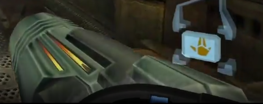
In the Metroid Prime 1 game, the arm cannon has 4 modes.
- Power Beam, Fully Retracted
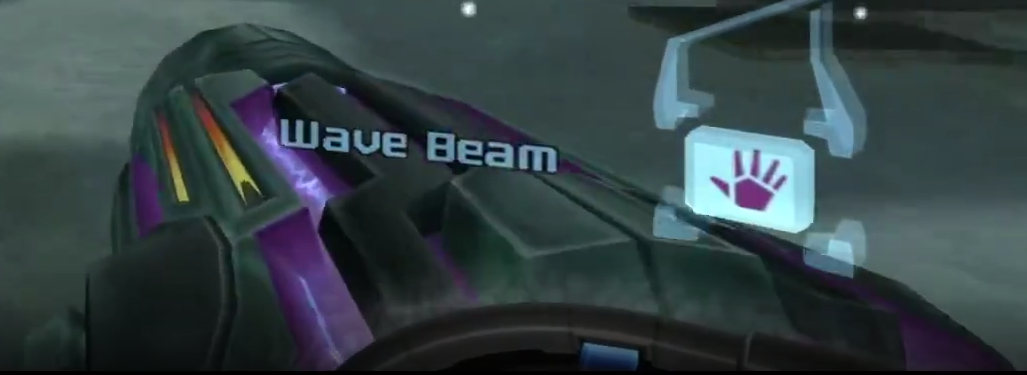
- Wave Beam, Sides Extended
- Ice Beam, Top Extended
- Plasma Beam, Tip Extended


To active this transformation, embedded electronics are required inside of the arm cannon prop. I needed a motor to provide the motion, a microcontroller to control the motion, some electronic components to carry the power, a power source, and a frame to attach everything. Before design or construction could begin, the specific components needed for the arm cannon prop had to be determined.
- For the motors, I used some surplus bipolar stepper motors found at Skycraft Parts and Surplus, a store in Winter Park, Florida.
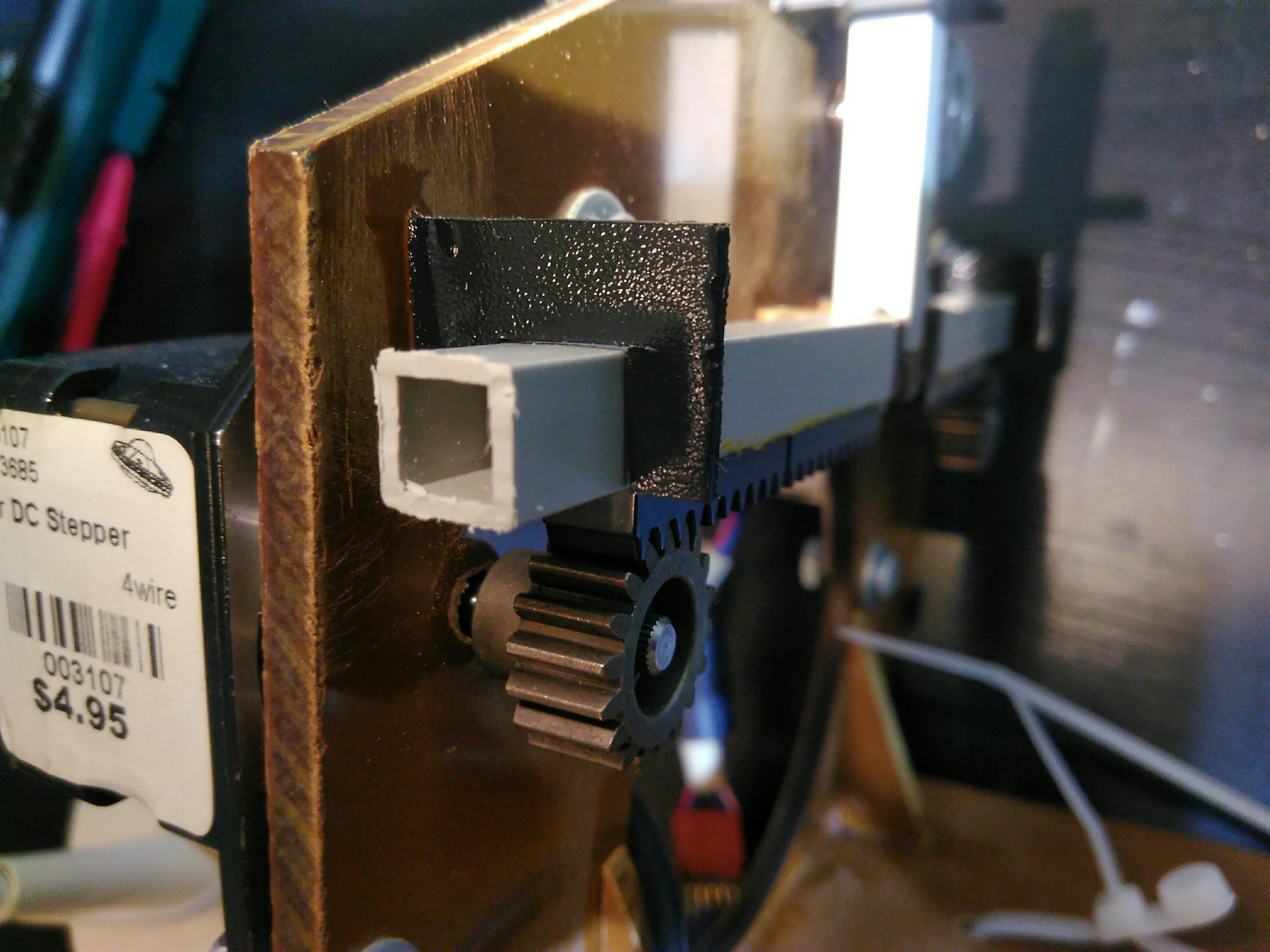
- For the power train, I attached a Traxxas 6491X 18-T Pinion Gear, 1.0 Metric Pitch to the shaft of the stepper motor with the set screw built in to the gear, and used a LEGO gear rack to convert the rotational motion to linear motion.
- For the microcontroller, I used an Arduino UNO.
- For the electronic components, I needed MOSFET transistors that cound be switched on by the microcontroller to carry the motor current. I also needed a H-bridge component to perform the current switching needed to drive the stepper motors. I specifically chose FQP30N06L MOSFET transistors and SN754410 H-Bridges.
- For the power source, I used a 10,000 mAh external phone battery.
- For the frame, I used phenolic plastic. I made this choice because hot electronics and motors will be mounted to this frame so it needs to be heat resistant, it will be on my arm so it needs to be lightweight, and the mechanical linkages needs to not be disrupted so it needs to be stiff (to minimize deflections). Phenolic plastic meets these criteria, while being machinable and relatively cheap.
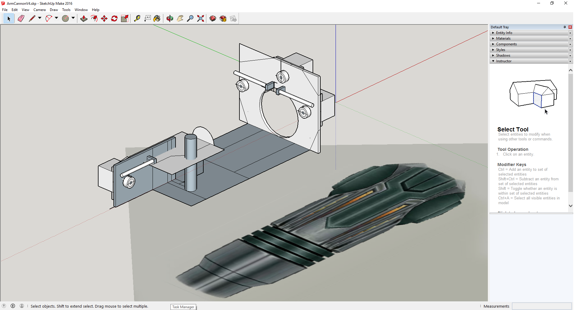
The first thing I needed to do was to create the frame for the arm cannon that everything would be strapped to. After taking some measurements of my arm, I used Sketchup to model the entire assembly. An image of the sketch is to the side.
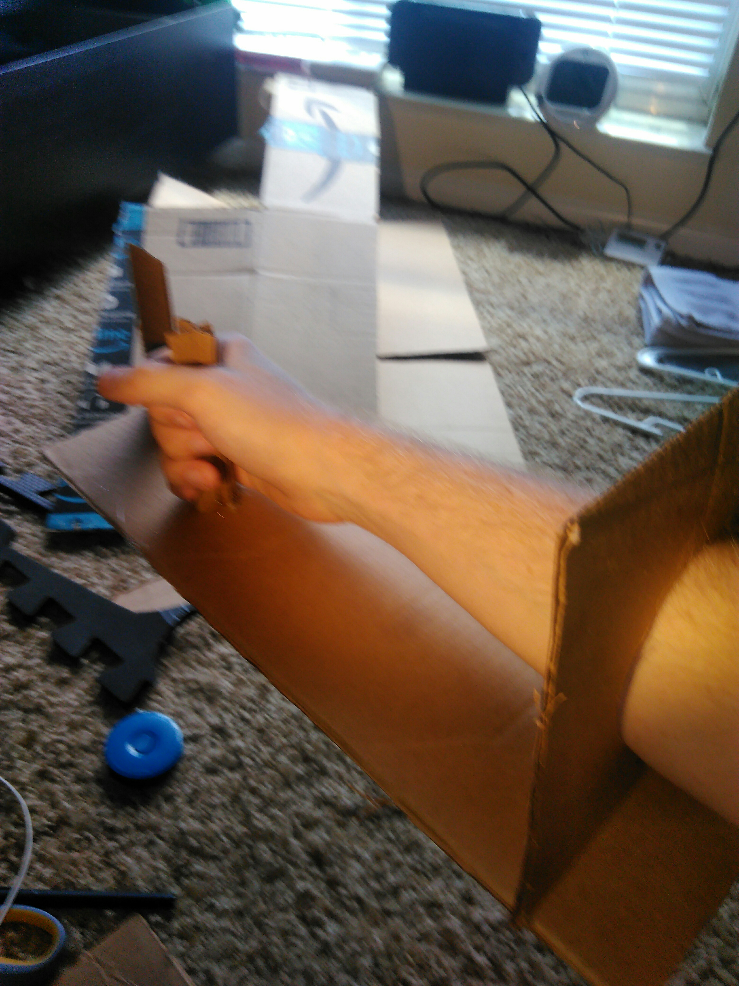
Next, I created a prototype of the arm cannon frame using cardboard, to ensure the fit was good. From the prototype, I learned that I needed to make the opening for my arm a bit larger, so it was comfortable to move around
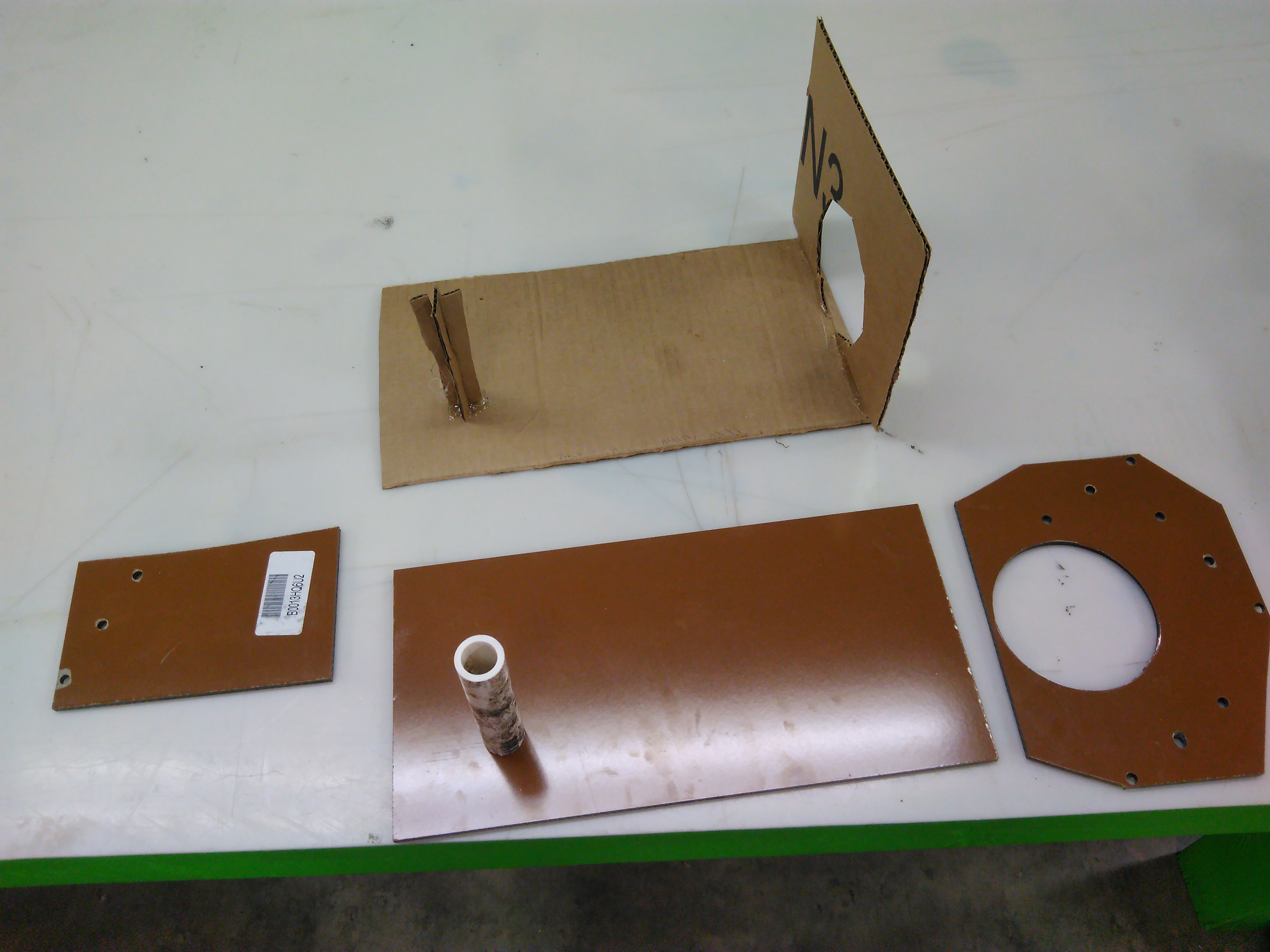
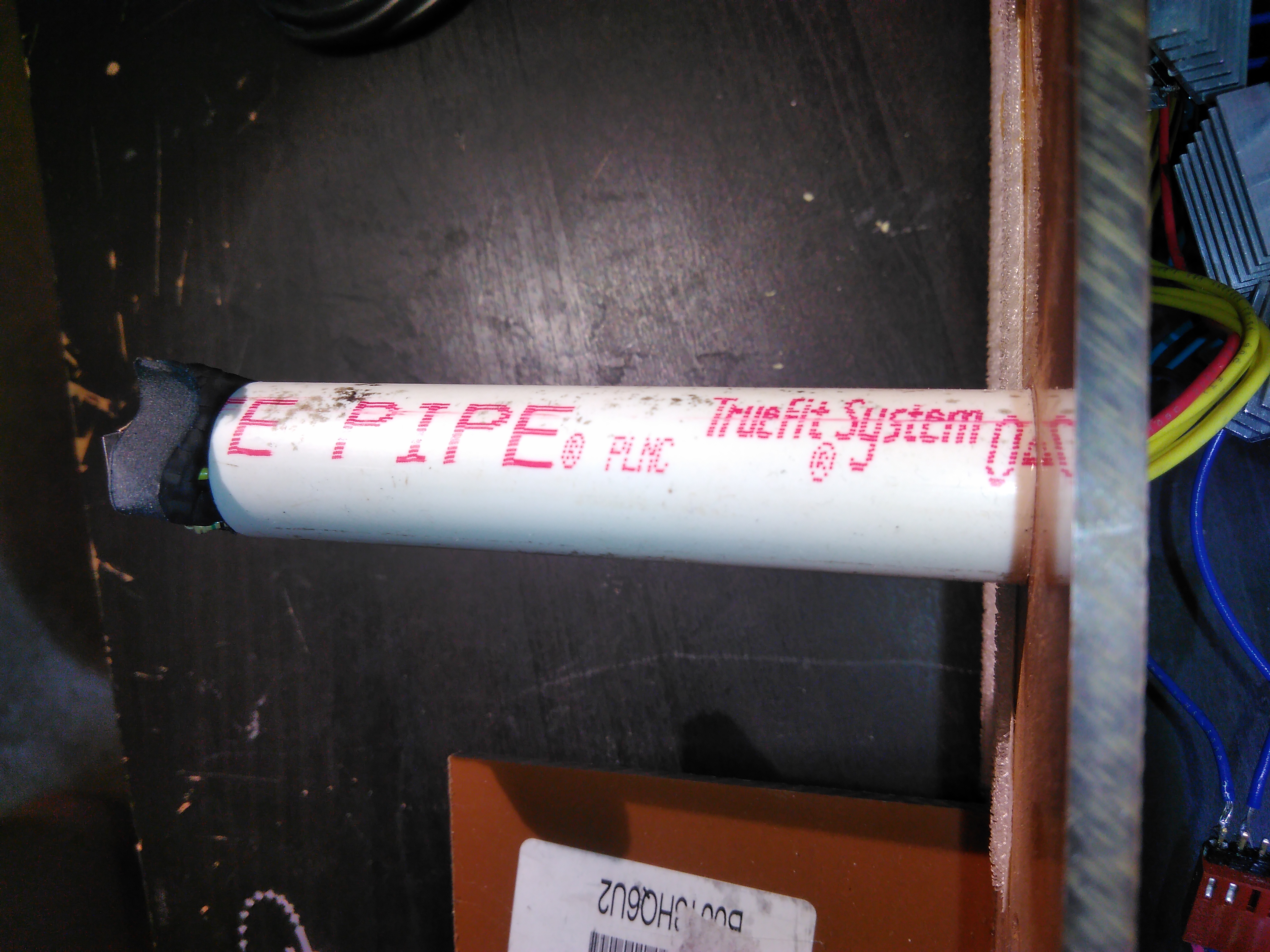
Using a locally available hackerspace, Knoxmakers, I machined out the phenolic plastic using a band saw and a drill press. I assembled the pieces using super glue, making sure to roughen the surfaces with sandpaper first. The PVC pipe was attached with E6000 glue.
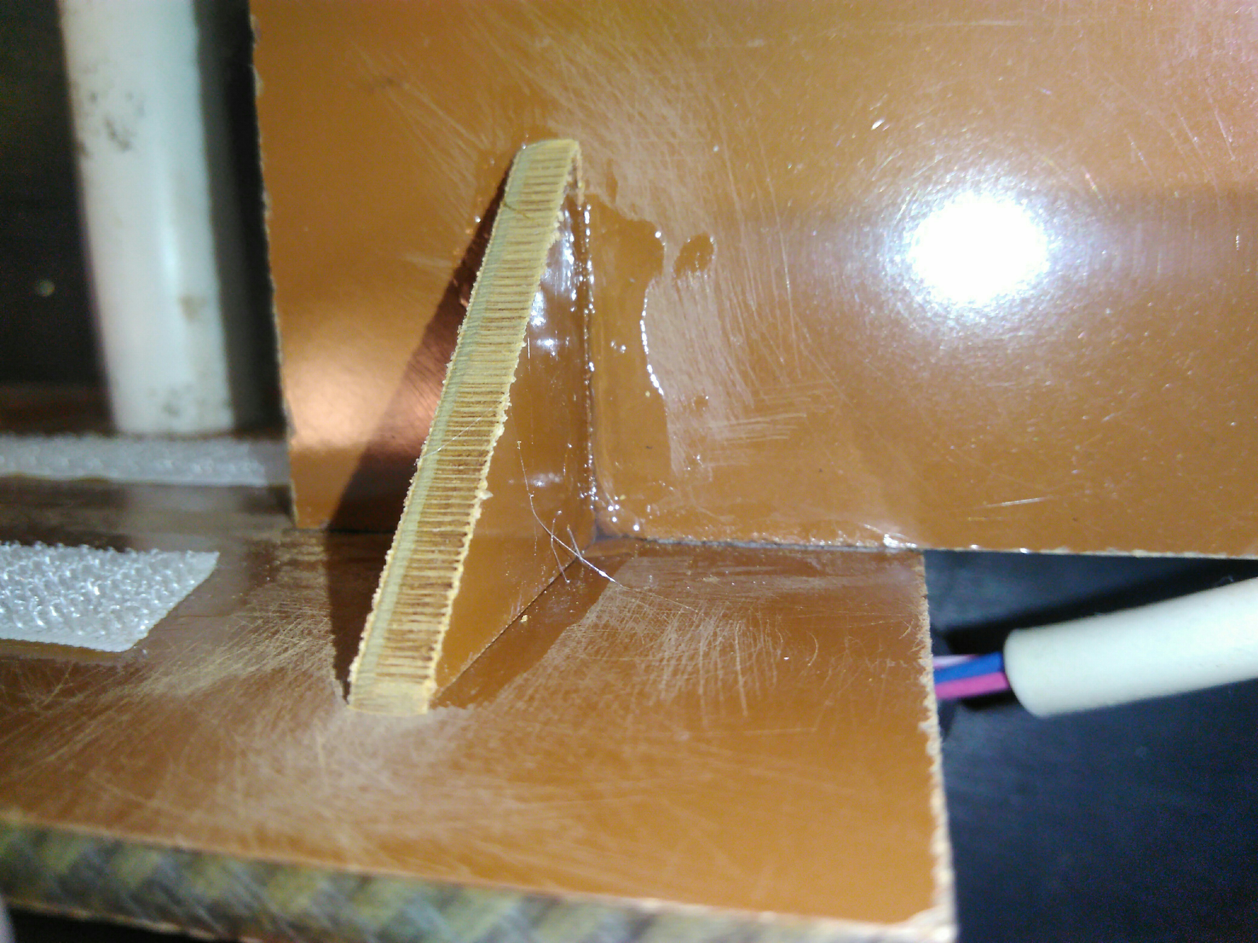
To provide further structural support, the leftover triangular pieces from trimming down the arm hole piece were used as supports. The angles of the larger pieces were not perfect 90 degree angles, so when the triangle supports were added, there was some gap between the surfaces. Super glue is not very thick and could not adhere the surfaces across the gap, so a thicker glue was used instead, E6000. However, E6000 takes longer to set, so super glue, which sets nearly instantly, was used to set and hold the pieces in place so the E6000 could dry. Also, E6000 emits organic solvents as it dries, so any time I glue something with E6000 I leave it in my ventilated bathroom.
Straight movement is desired, so a linear guide rail needs to be attached to the frame. This was achieved by using a ABS plastic box tube around a Teflon rod to minimize friction. The teflon rod was secured to the phenolic plastic by using a machine screw pinned connection. This allows the ABS plastic box tube to slide over the rod. The moving panels of the arm cannon prop will be attached to this ABS plastic box tube.
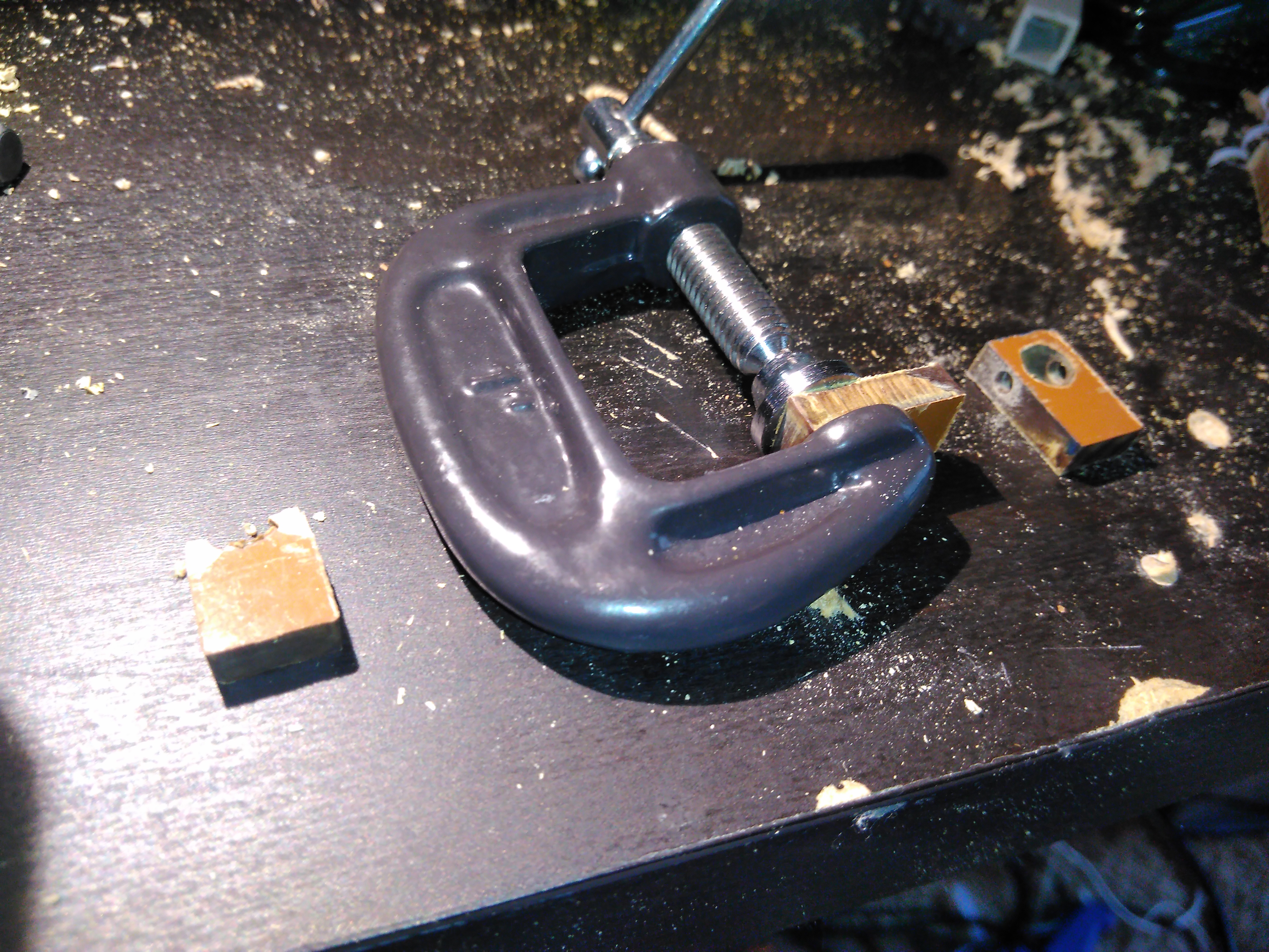
Drilling the holes for the machine screw pinned connection caused the phenolic plastic to split, so a clamp held the phenolic plastic together.
Clearer image of the pinned connection method.
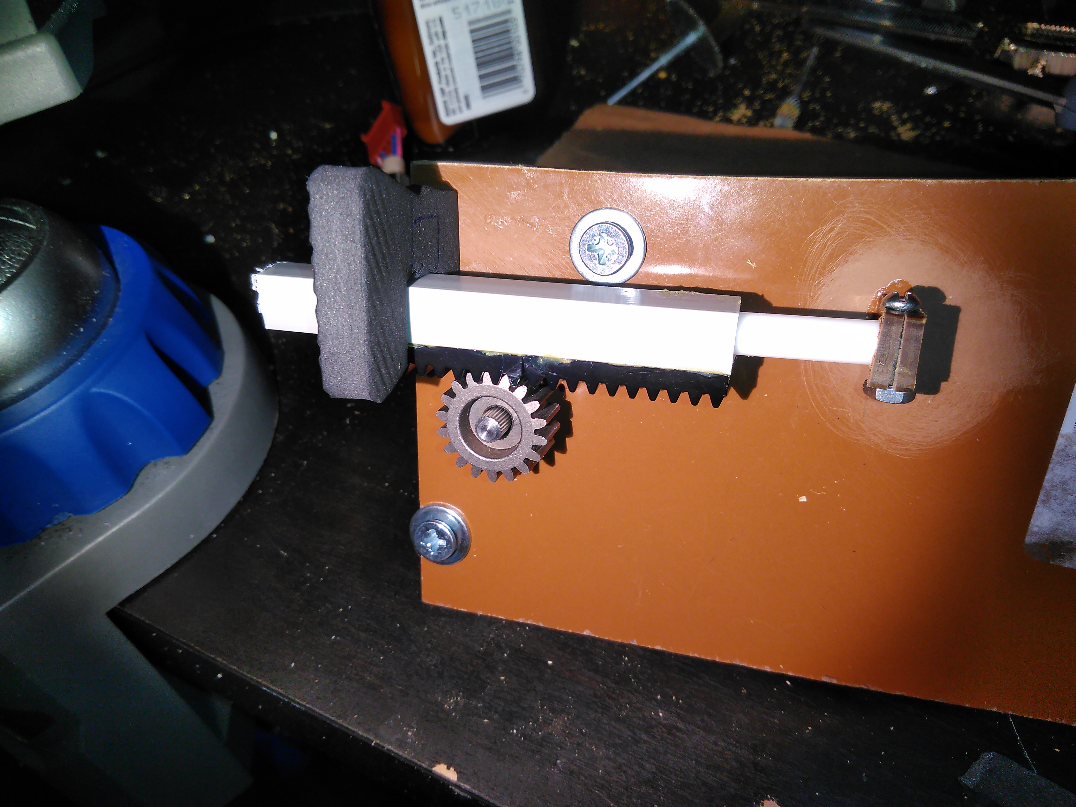
A test of the linear guide system was performed by attaching the Teflon guide rods to the frame, the stepper motor was screwed on and the gear with the set screw was attached to the motor shaft, and the ABS plastic box tube and the LEGO gear rack (Also made from ABS plastic) was slid on to test the gear teeth fit.
The LEGO gear rack was attached to the ABS plastic box tube using contact cement.
With the framework of the arm cannon prop completed, the electronics of the prop can be completed. Below is the electrical diagram of the arm cannon controls.
- Red wires are live, carrying 5V relative to ground.
- Black wires lead to ground.
- Yellow wires either receive signal from the buttons, or turn on the MOSFET transistors.
- Green wires control the H-Bridge logic.
- Blue wires carry power for the bipolar stepper motors.
 Click to download the .tex code that generated the electrical diagram
This entire project was done very incrementally. First, the
stepper motors had to be tested to ensure they worked, and to confirm
that they are bipolar. Alternating pairs of the 4 wires were tested
until the individual poles could be identified and the power sequence could be determined.
A 9V battery was used for this purpose.
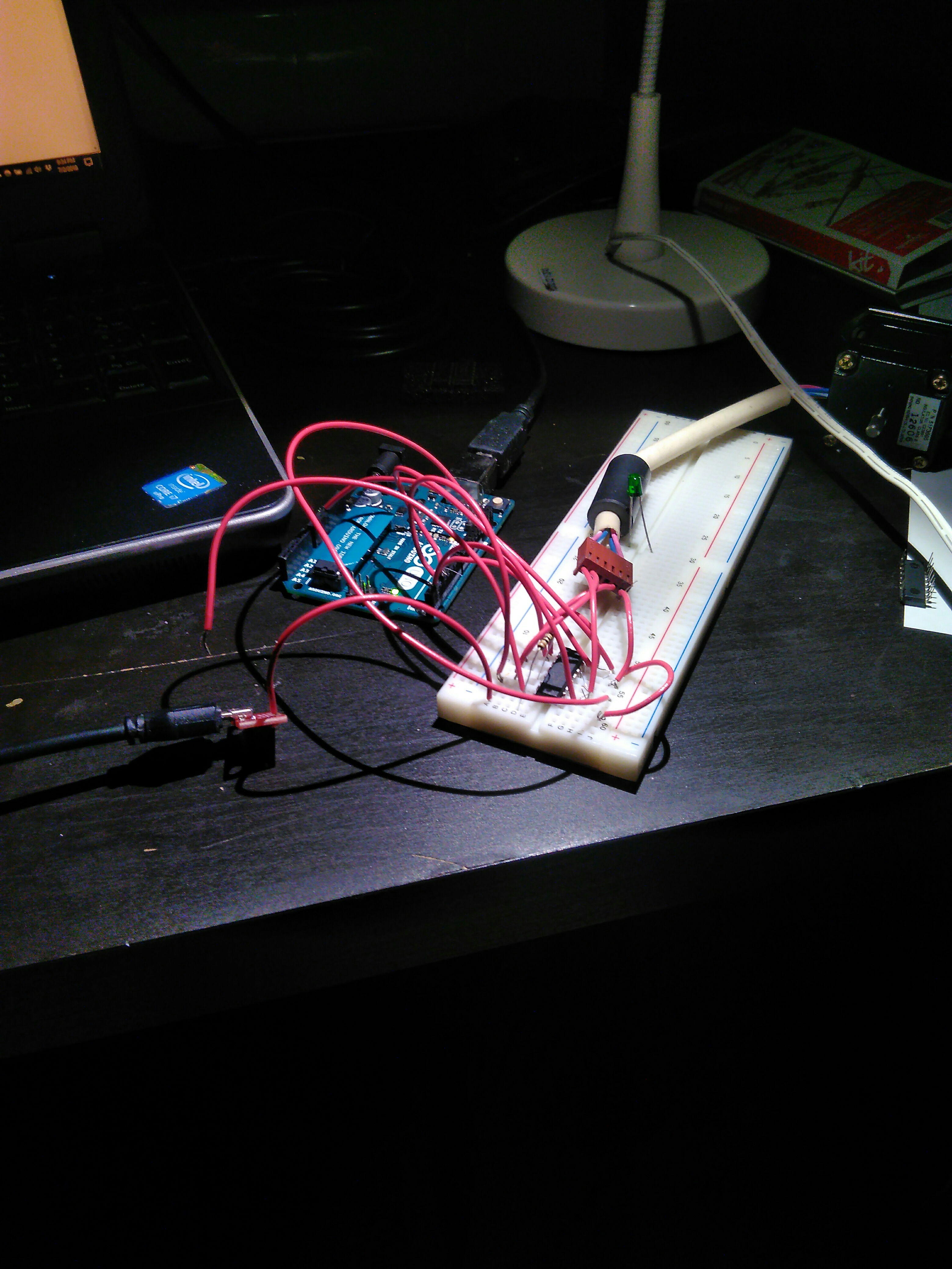
Then, the H-Bridges were
tested using a breadboard. Following the datasheet, I manually powered on the
appropriate pins by touching the bare wires to the terminals of a battery,
and used it to turn a stepper motor one step at a time.
Next, I had to sit down and learn how to program the Arduino. I wrote a
simple program to just loop and constantly drive the H-bridge pins.
This was a success, but I had strange issues with driving the motor.
The symptoms included:
1. The stepper motor would drive just fine for about 30 seconds.
2. But then it would start skipping steps, even at very low rotation speeds.
3. When I grasped the gear to feel the torque, on some steps it would fail to exert much force.
4. The motor would emit a low whine noise.
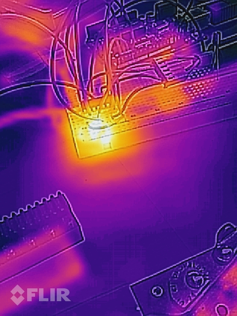
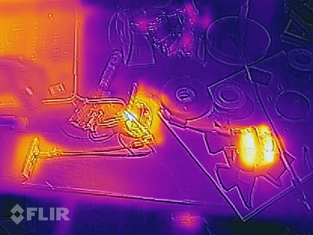
I did not figure out the problem until someone at the Knoxville makerspace asked if I
had physically felt the H-Bridge. They recognized the symptoms from their
attempts to make a 3D printer. The H-Bridge was very, very hot and was failing.
Looking back at the spec sheets, the H-Bridge was only rated for 1 Amp of current.
When I measured the current draw of the motors, they were drawing 1.5 Amps.
I could have obtained H-Bridges that were rated for higher current, but
I decided to jury rig them instead, and strap some heat sinks on them.
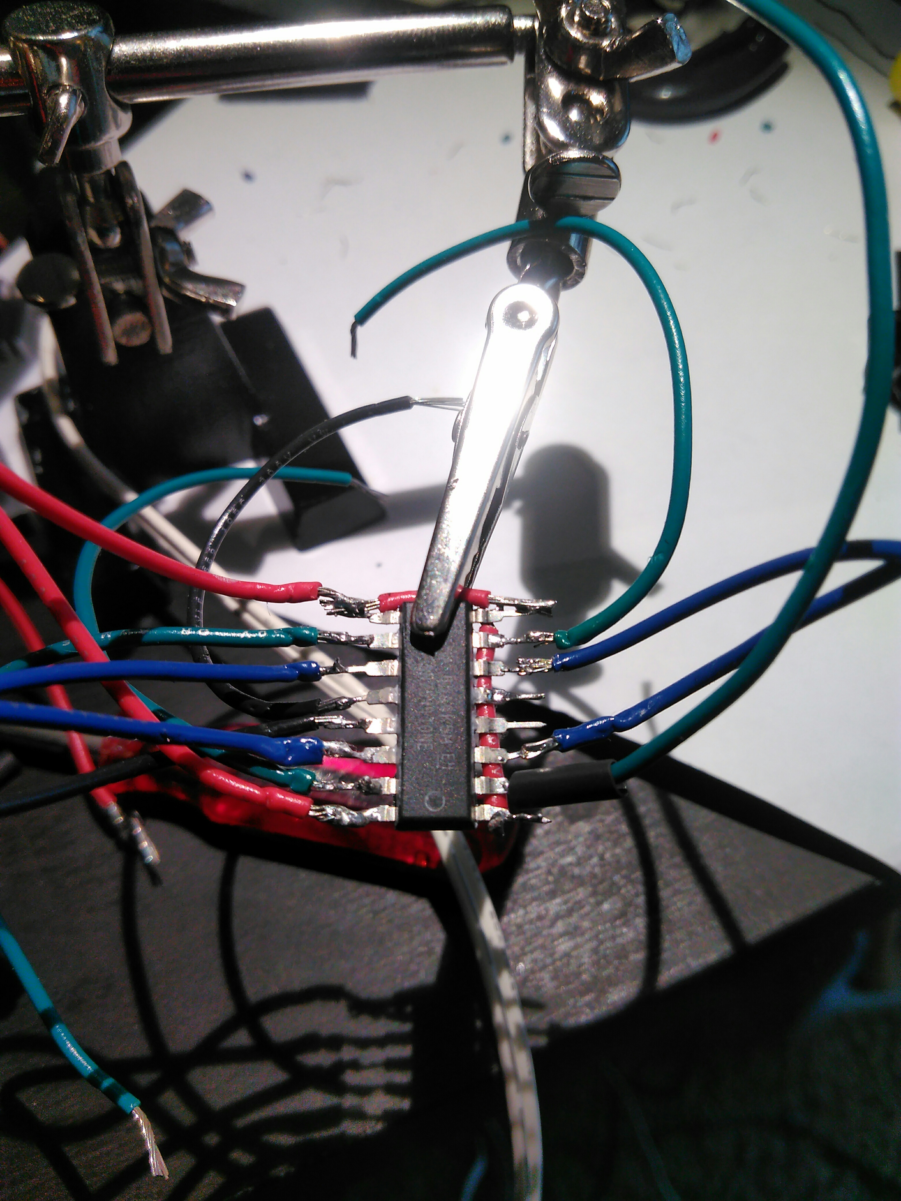
To prepare the H-Bridges for the heat sinks, I had to flatten out the pins, and solder wires on them. I only knew the very basics of soldering, and this forced me to learn more.
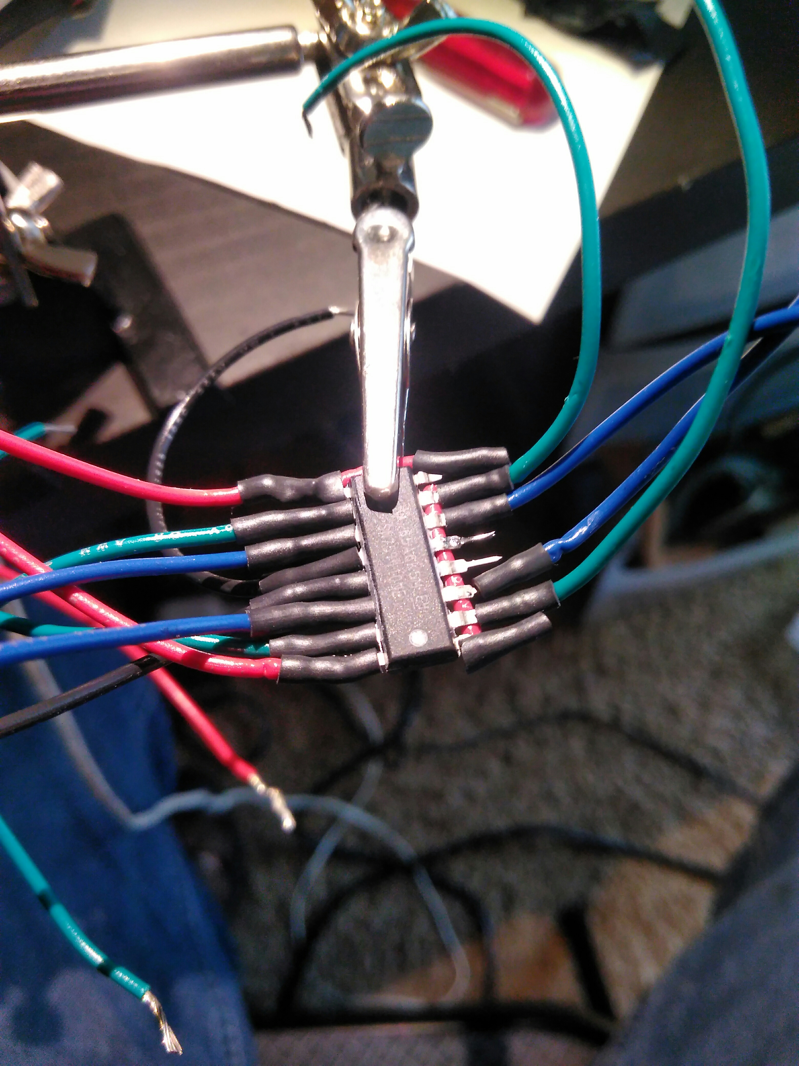
I was planning on using aluminum heat sinks, so I was concerned with potential short circuits, and I was worried about the mechanical strength of the connections. To solve this, I used heat shrink tubing.
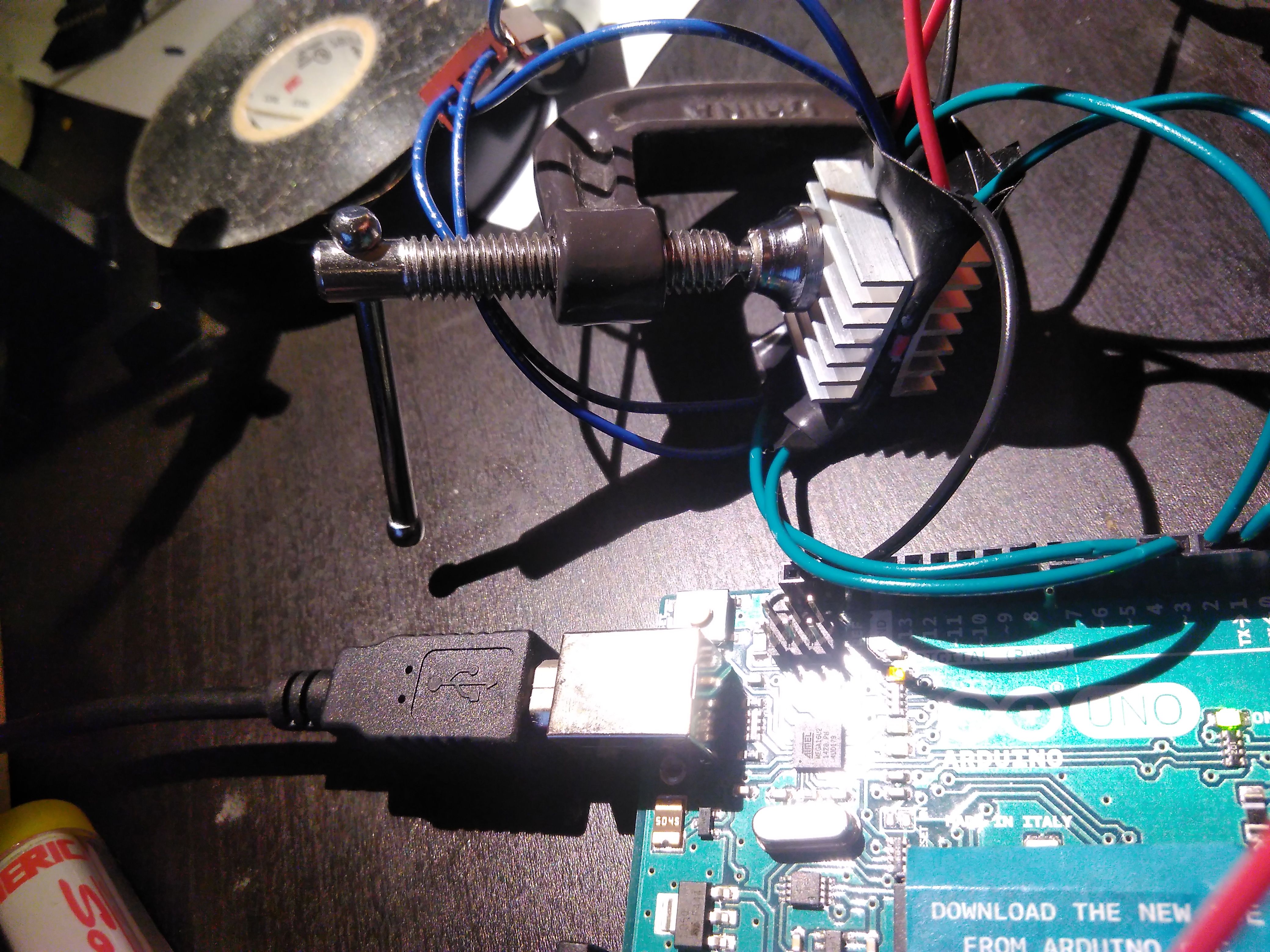
Before adhering the heat sinks on the H-Bridge, I performed a test to make sure the heat sink idea would actually work. The test was a success, but there was still some uncertainty on whether the success was due to the metal clamp providing additional needed heat sink area, or if the aluminum heat sink was enough.
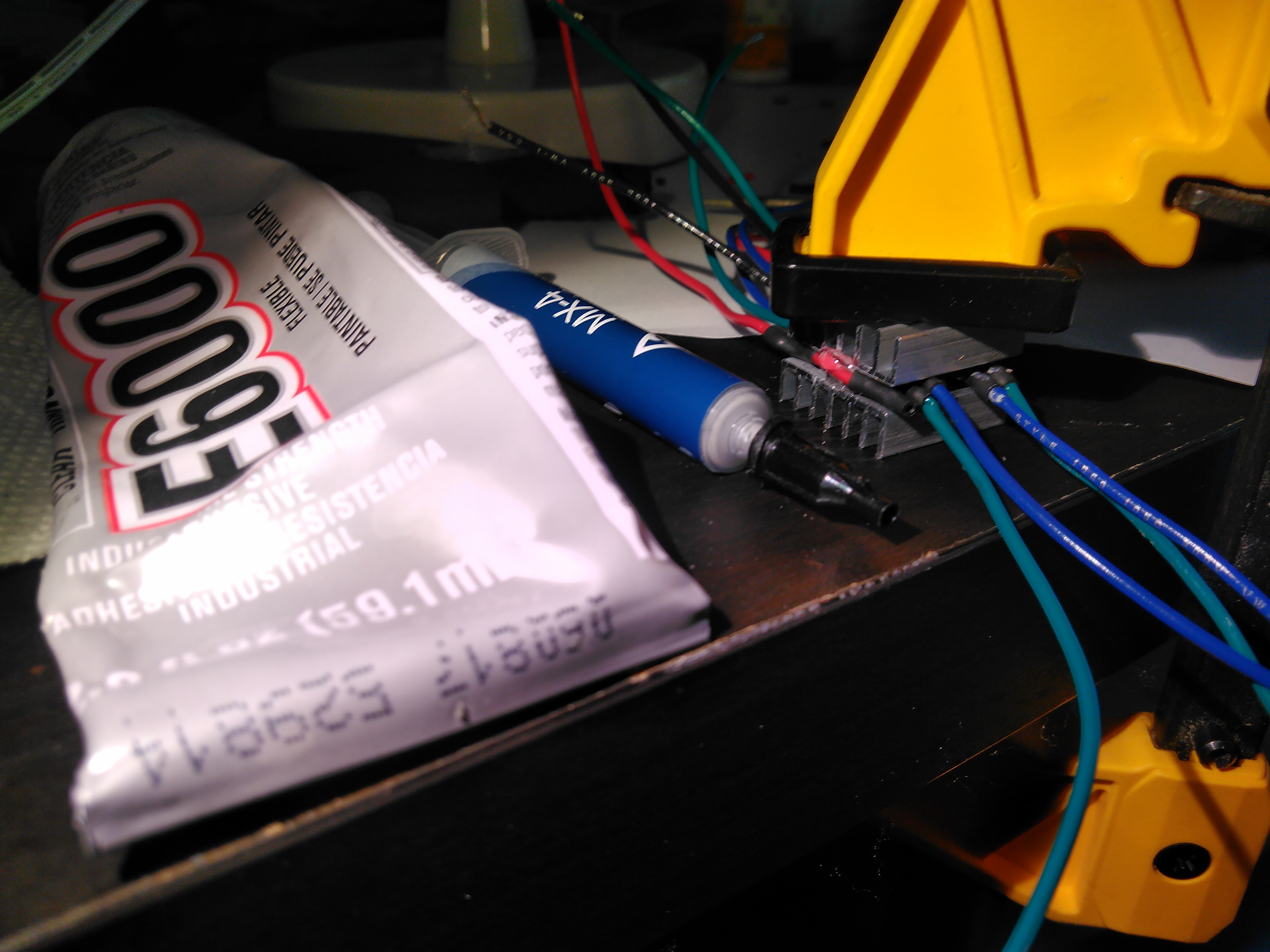
When attaching the heat sinks, I wanted to ensure a good thermal connection, so I got some thermal paste. I learned a valuable lesson on the difference between thermal paste and thermal adhesive. Thermal paste stays liquid forever, and does not work for my case, while thermal adhesive actually adheres the two surfaces together. I got a tube of thermal adhesive, but I went a little too cheap and the glue was not very strong. A small dot of E6000 helped with the adhesion, but for the next project I need to use thermal heat conductive epoxy instead.
With the heat sink attached, I was able to test the H-Bridge, and everything worked. The stepper motor no longer skipped steps.
The video below shows the motor working and driving a LEGO piece back and forth. I altered the Arduino code so the motor would rotate back and forth instead of continuously in one direction.
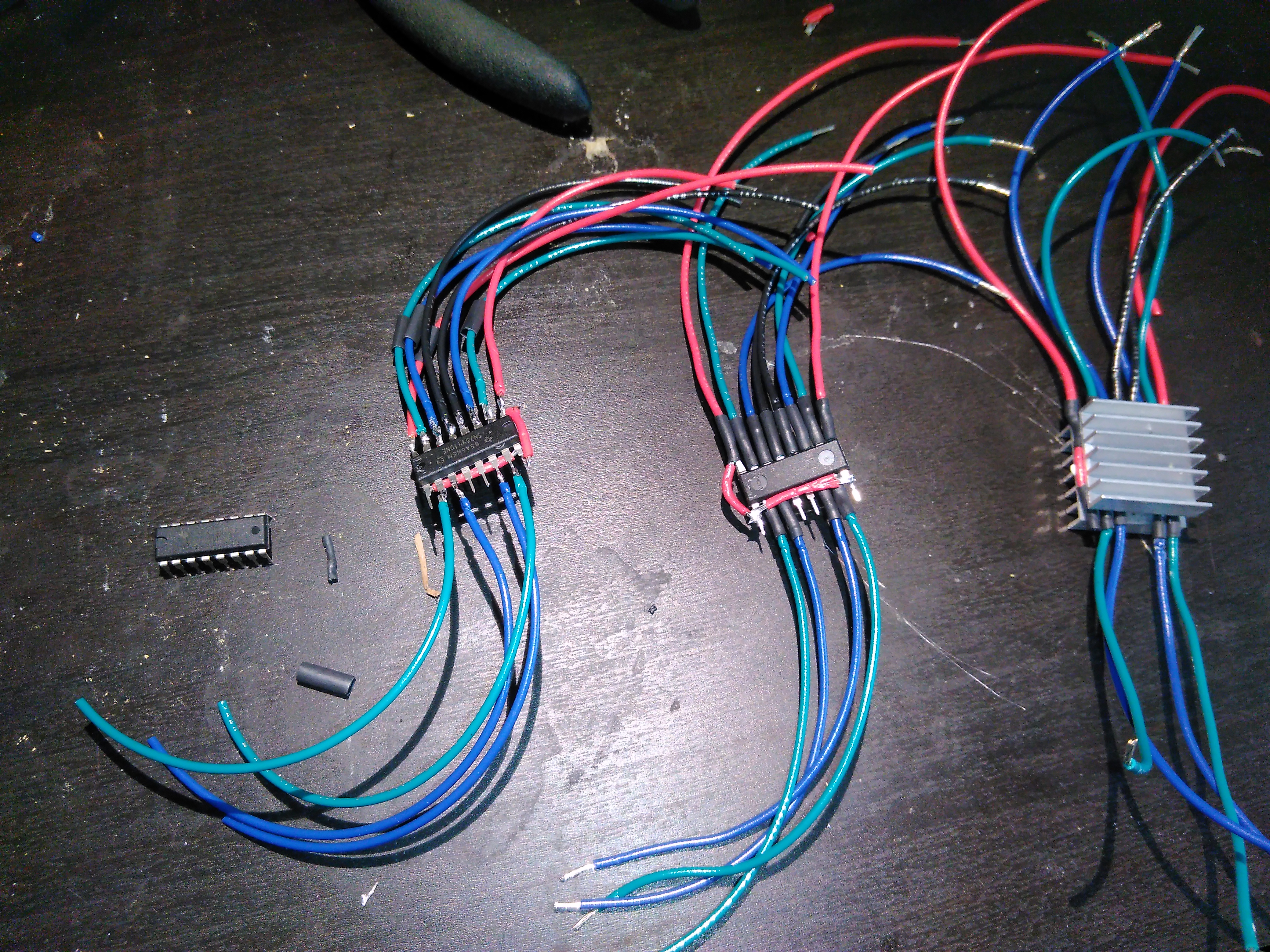
With the proven success of one of the H-Bridges, I went and assembled the other three H-Bridges.
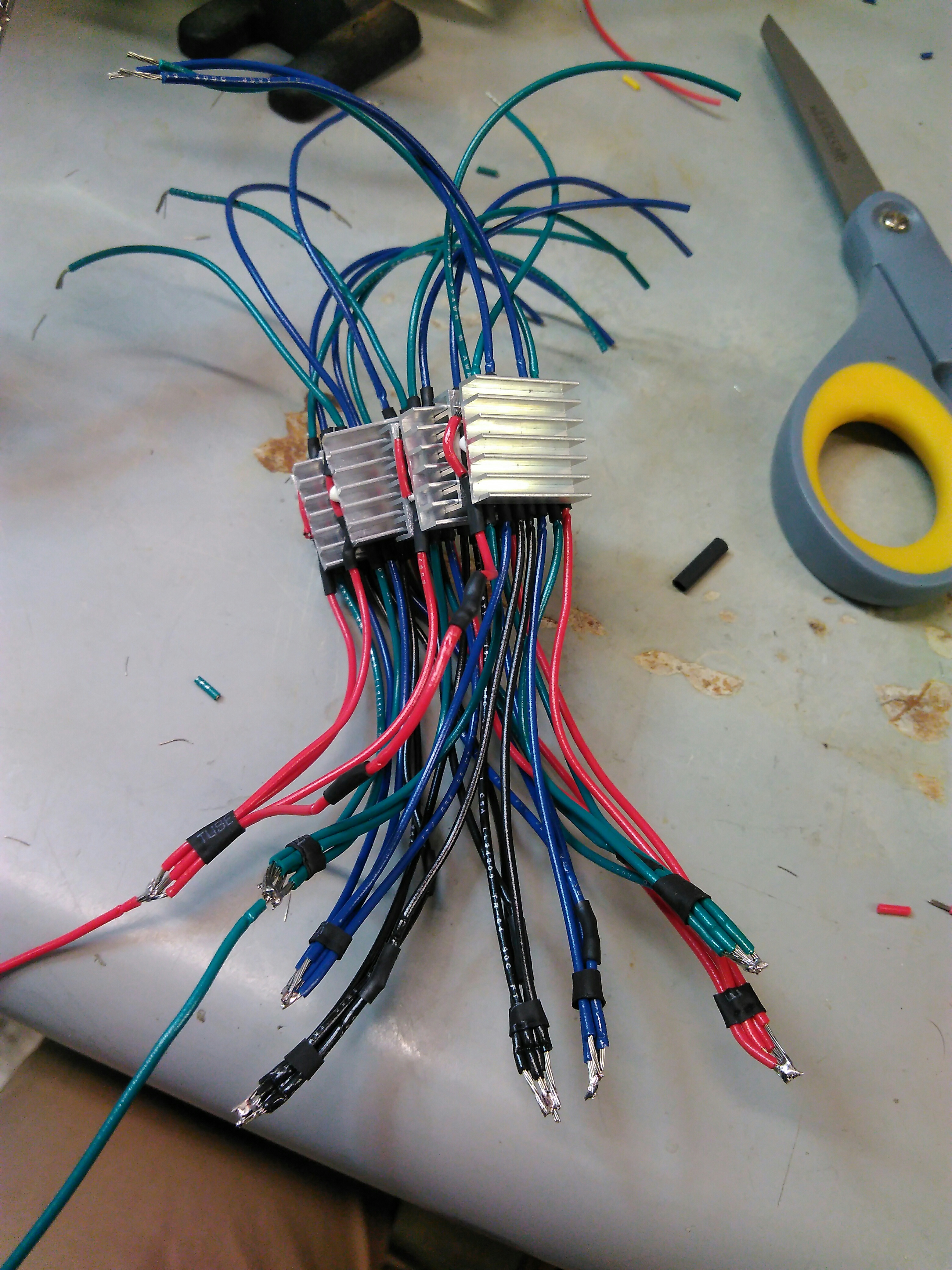
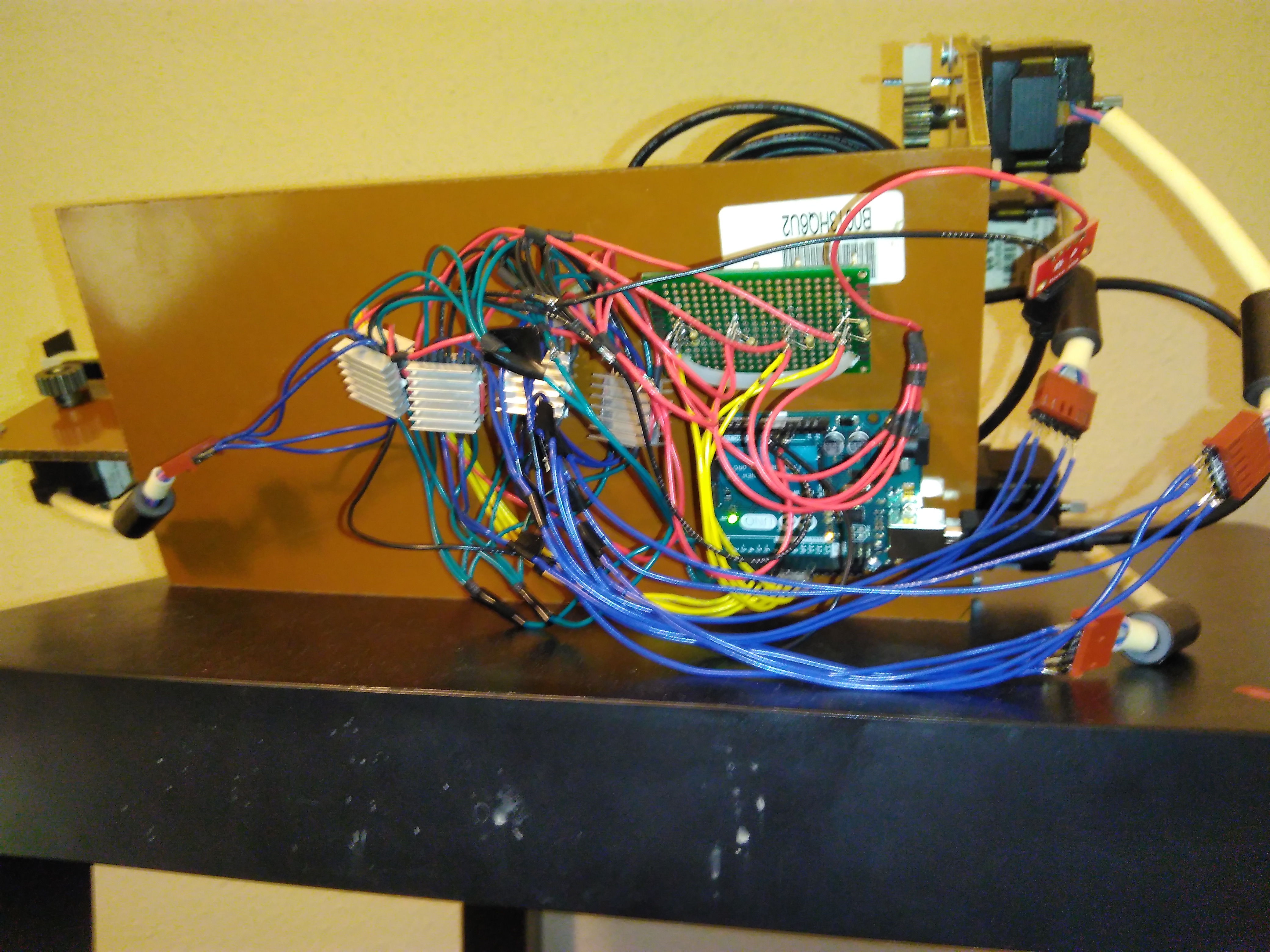
I started assembling the wiring together. I started with the H-Bridges. I merged some of the wires together, but I did not think about the wire geometry enough. I nearly did not have enough length on the wires to make everything work, and to keep the H-bridges separates requires putting some tension on the wires. I used heat shrink tubing to try to protect the exposed wires.
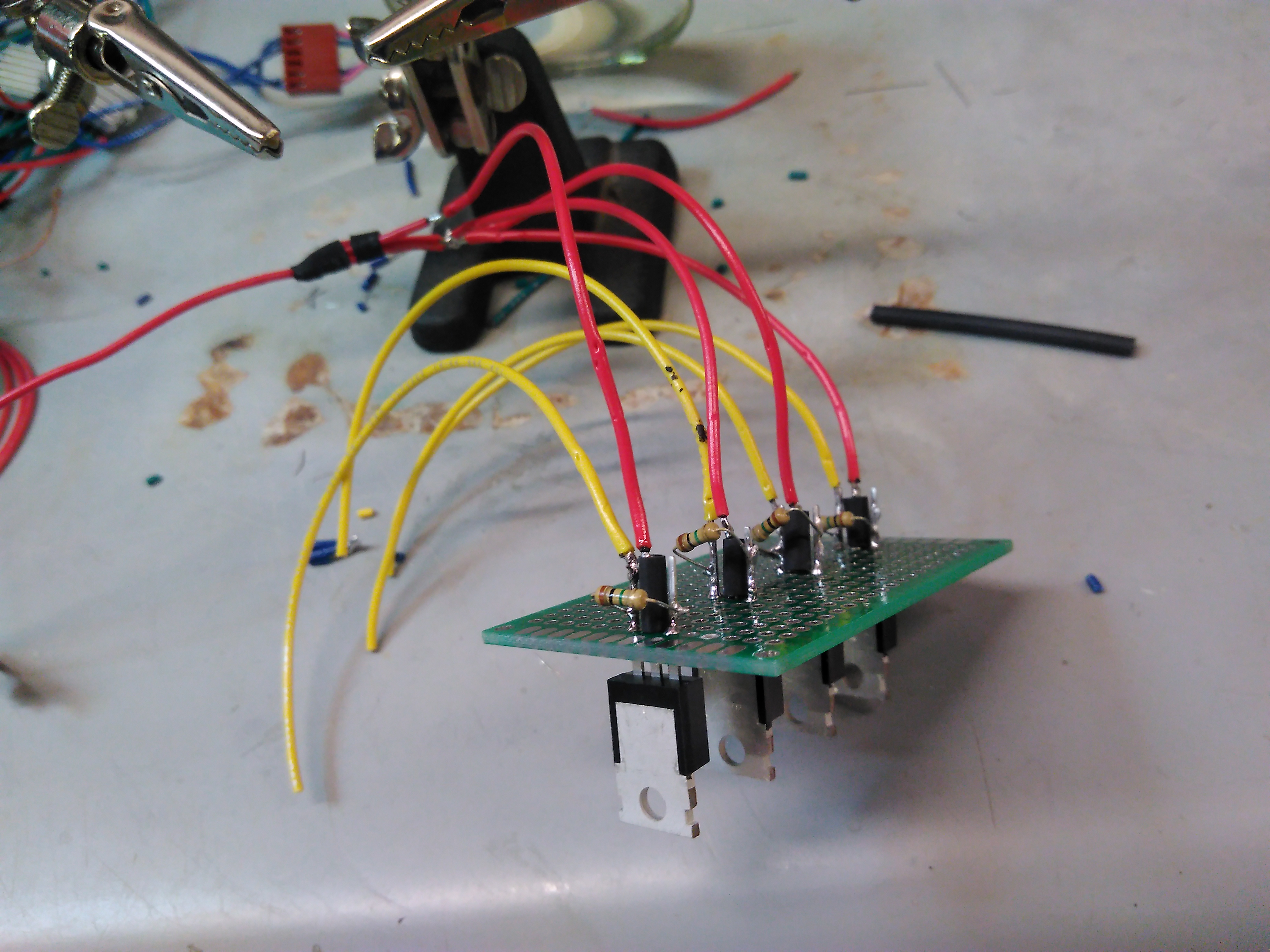
Next, I soldered the MOSFET transistors to a spare PCB board with lots of holes. At first, I did not include the resistors. This caused strange behavior where the MOSFET transistors could be switched on, but would not switch off when the gate was sent back low, the transistor was stuck in the on state. This behavior is caused by a buildup of charge at the gate, and the gate needs to be "pulled" to a voltage to prevent this sticky behavior. A high resistance resistor connected to the source pin is enough to drain the charge away after the gate voltage is sent low. The lesson I learned is that "pulldown" resistors are frequently required in circuits.
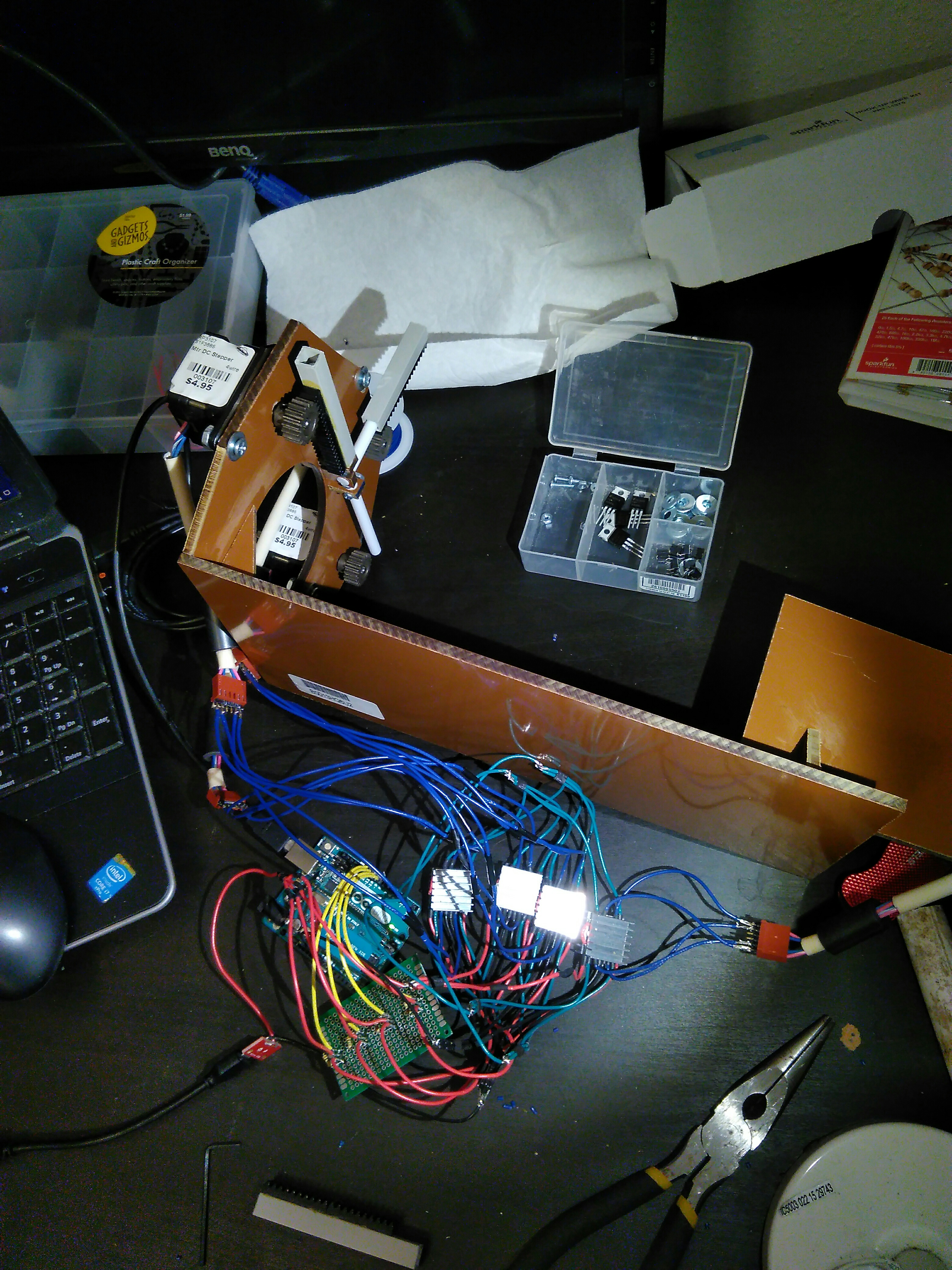
Next, I connected everything to the motors and the Arduino. My technique was to solder the loose wires to header pins, because these header pins can be plugged directly into the Arduino, and directly into the stepper motor.
With everything connected, I could test the ability of the electronics to drive the shafts. Here I learned that the Teflon rod is not very rigid, so it can deflect. When the box tube is at maximum extension, the Teflon rod can laterally bend enough to cause the box tube to fall off the gear. In addition, the box could rotate around the teflon tube and cause the LEGO gear rack to point the wrong way. To solve this, an ABS plastic restraint was attached to the phenolic plastic frame. This restraint has a U shape to prevent lateral movement, and straight sides to prevent rotation.
The video of my mechanical drive test is shown below.
The next task was to wire up the buttons so I could control the arm cannon prop configurations. I chose to run the wires inside of the PVC pipe, and connect to the buttons from the bottom. When testing the buttons, I ran into the same problem I did with the MOSFET transistors, where if I pushed the button once, it seemed to stay on even after I released it. Again, charge was being trapped in the digital pins of the Arduino, and the solution was a high resistance pulldown resistor that connected the pins to ground.
With everything wired up, all I had to do was attach the electronics to the phenolic plastic frame. A combination of zip ties through holes, and machine screws through holes got everything in place.
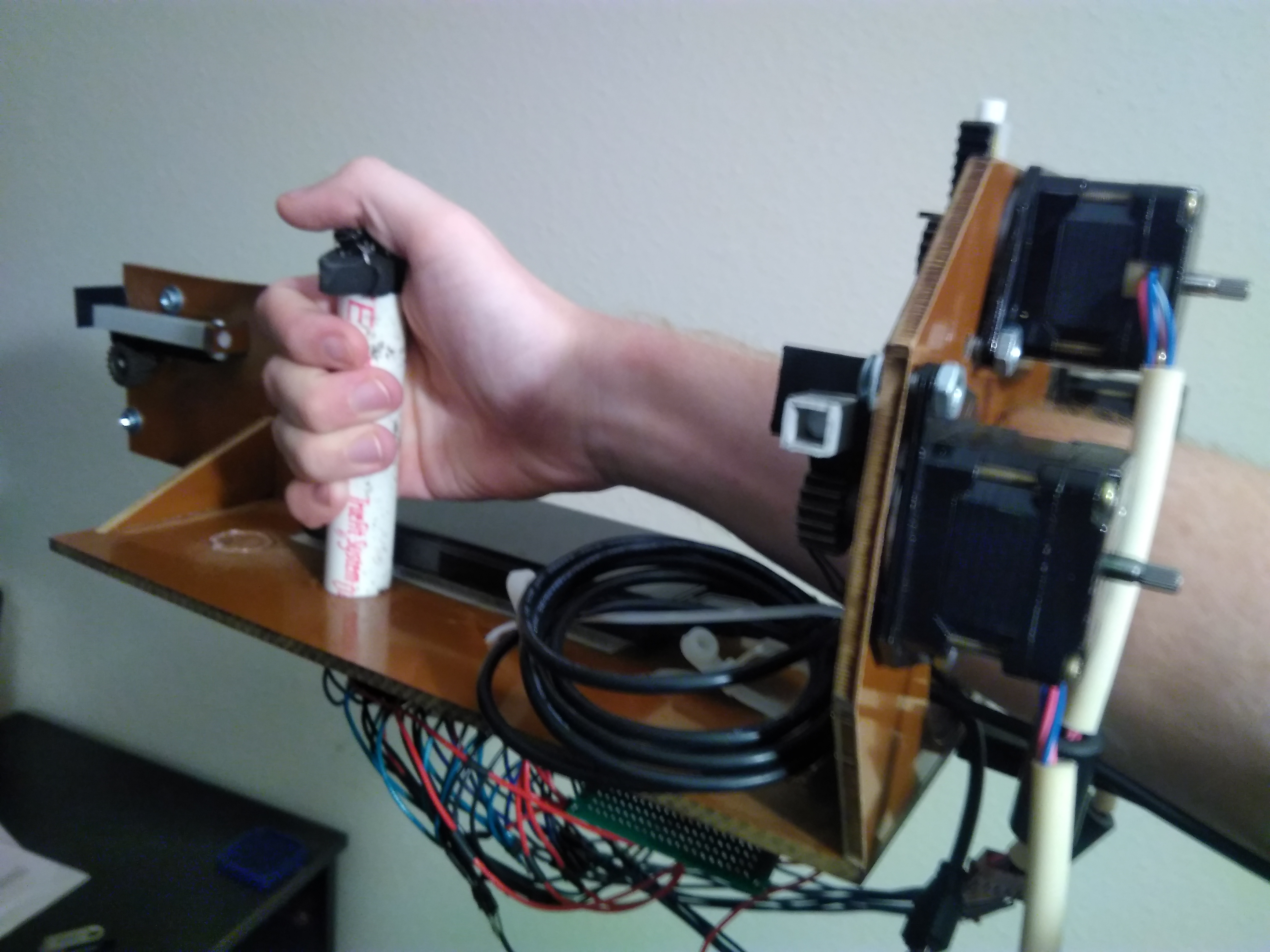
Using contact cement, I attached soft velcro to the 10,000 mAh battery and attached hook velcro to the phenolic plastic frame, so the battery would stay in place. Now the arm cannon prop can be moved around and no longer has to be on a table.
The following code is the Arduino code that runs the arm cannon code. When a button is pressed, the arm cannon prop takes on that configuration, then waits for another button press. When in the power beam configuration, all the transistors are turned off, saving battery life and preventing heat buildup. Small magnets will be used to keep the arm cannon prop all closed up in the power beam configuration so the mobile parts do not get jostled loose. When the arm cannon is in an extended position, current is constantly run through the motor to hold it in place. The battery could hold the motors in place for hours. For the wave configuration, two stepper motors are powered. The 10,000 mAh battery has trouble providing the 3 Amps needed to power these motors. It still works and can still provide enough power to hold the motors in place, but to prevent skipping of steps as the arm cannon prop extends or retracts, the stepDelay must be high enough.
  1 // This code controls a Samus Aran arm cannon prop from Prime 1.
  2 // It drives stepper motors to move the arm cannon prop to
  3 // the 4 main configurations shown in the game.
  4 // Buttons by the thumb of the user are used to select the arm cannon prop configuration
  5
  6 //###
  7 //Code Written by:
  8 //Kyle Shepherd
  9 //KyleAnthonyShepherd@gmail.com
 10 //August 30, 2018 (Version 1)
 11 //###
 12
 13 // output to control the H-Bridges to step the motors
 14 int outA1 = 0;
 15 int outA2 = 1;
 16 int outB1 = 2;
 17 int outB2 = 3;
 18
 19 // output to control motor power through a MOSFET
 20 int MOSFET4 = 11;
 21 int MOSFET3 = 10;
 22 int MOSFET2 = 9;
 23 int MOSFET1 = 8;
 24
 25 // input to control arm cannon position
 26 int BEAM = 4;
 27 int WAVE = 5;
 28 int ICE = 6;
 29 int PLASMA = 7;
 30
 31 // variables to store the state of the arm cannon
 32 int BEAMBUTTON = 0;
 33 int WAVEBUTTON = 0;
 34 int ICEBUTTON = 0;
 35 int PLASBUTTON = 0;
 36
 37
 38 int stepDelay = 20; // Delay between motor steps in milliseconds
 39
 40 // defining the value above as inputs or outputs
 41 void setup() {
 42   pinMode(outA1, OUTPUT);
 43   pinMode(outA2, OUTPUT);
 44   pinMode(outB1, OUTPUT);
 45   pinMode(outB2, OUTPUT);
 46   pinMode(MOSFET1, OUTPUT);
 47   pinMode(MOSFET2, OUTPUT);
 48   pinMode(MOSFET3, OUTPUT);
 49   pinMode(MOSFET4, OUTPUT);
 50   pinMode(BEAM, INPUT);
 51   pinMode(WAVE, INPUT);
 52   pinMode(ICE, INPUT);
 53   pinMode(PLASMA, INPUT);
 54 }
 55
 56 // functions elaborating the pin output patterns needed
 57 // to drive the H-bridge and the motors
 58 void step1() {
 59   digitalWrite(outA1, LOW);
 60   digitalWrite(outA2, HIGH);
 61   digitalWrite(outB1, HIGH);
 62   digitalWrite(outB2, LOW);
 63   delay(stepDelay);
 64
 65 }
 66 void step2() {
 67   digitalWrite(outA1, LOW);
 68   digitalWrite(outA2, HIGH);
 69   digitalWrite(outB1, LOW);
 70   digitalWrite(outB2, HIGH);
 71   delay(stepDelay);
 72 }
 73 void step3() {
 74   digitalWrite(outA1, HIGH);
 75   digitalWrite(outA2, LOW);
 76   digitalWrite(outB1, LOW);
 77   digitalWrite(outB2, HIGH);
 78   delay(stepDelay);
 79 }
 80 void step4() {
 81   digitalWrite(outA1, HIGH);
 82   digitalWrite(outA2, LOW);
 83   digitalWrite(outB1, HIGH);
 84   digitalWrite(outB2, LOW);
 85   delay(stepDelay);
 86 }
 87
 88 // holds the motor at the step 1 condition
 89 void hold() {
 90   digitalWrite(outA1, LOW);
 91   digitalWrite(outA2, HIGH);
 92   digitalWrite(outB1, HIGH);
 93   digitalWrite(outB2, LOW);
 94   delay(stepDelay);
 95 }
 96
 97 // function to step the motor forward one complete increment
 98 void forward() {
 99   step1();
100   step2();
101   step3();
102   step4();
103 }
104
105 // function to step the motor backward one complete increment
106 void reverse() {
107   step4();
108   step3();
109   step2();
110   step1();
111 }
112
113 // the loop routine runs over and over again forever:
114 void loop() {
115   // reads the state of the buttons
116   BEAMBUTTON = digitalRead(BEAM);
117   WAVEBUTTON = digitalRead(WAVE);
118   ICEBUTTON = digitalRead(ICE);
119   PLASBUTTON = digitalRead(PLASMA);
120
121   if (PLASBUTTON == HIGH) { // move to PLASMA position
122     // turns on the needed transistors
123     digitalWrite(MOSFET4, HIGH);
124     digitalWrite(MOSFET3, LOW);
125     digitalWrite(MOSFET2, LOW);
126     digitalWrite(MOSFET1, LOW);
127     // perform 24 increments, to fully extend the arm cannon
128     for (int i=1; i <= 24; i++){
129       reverse();}
130
131     // gets into holding position
132     hold();
133     // waits for another button to be pressed
134     while(1) {
135       BEAMBUTTON = digitalRead(BEAM);
136       WAVEBUTTON = digitalRead(WAVE);
137       ICEBUTTON = digitalRead(ICE);
138       if (BEAMBUTTON == HIGH || WAVEBUTTON == HIGH || ICEBUTTON == HIGH) {
139         // if another button is pressed, retract the arm cannon
140         for (int i=1; i <= 24; i++){
141           forward();}
142         // turns off power
143         digitalWrite(MOSFET4, LOW);
144         break;
145         }
146       }
147     }
148   // reads the state of the buttons
149   BEAMBUTTON = digitalRead(BEAM);
150   WAVEBUTTON = digitalRead(WAVE);
151   ICEBUTTON = digitalRead(ICE);
152   PLASBUTTON = digitalRead(PLASMA);
153   if (ICEBUTTON == HIGH) { // move to ICE position
154     // turns on the needed transistors
155     digitalWrite(MOSFET4, LOW);
156     digitalWrite(MOSFET3, HIGH);
157     digitalWrite(MOSFET2, LOW);
158     digitalWrite(MOSFET1, LOW);
159     // perform 14 increments, to fully extend the arm cannon
160     for (int i=1; i <= 14; i++){
161       forward();}
162
163     // gets into holding position
164     hold();
165     // waits for another button to be pressed
166     while(1) {
167       BEAMBUTTON = digitalRead(BEAM);
168       WAVEBUTTON = digitalRead(WAVE);
169       PLASBUTTON = digitalRead(PLASMA);
170       if (BEAMBUTTON == HIGH || WAVEBUTTON == HIGH || PLASBUTTON == HIGH) {
171         // if another button is pressed, retract the arm cannon
172         for (int i=1; i <= 14; i++){
173           reverse();}
174         // turns off power
175         digitalWrite(MOSFET3, LOW);
176         break;
177         }
178       }
179     }
180   // reads the state of the buttons
181   BEAMBUTTON = digitalRead(BEAM);
182   WAVEBUTTON = digitalRead(WAVE);
183   ICEBUTTON = digitalRead(ICE);
184   PLASBUTTON = digitalRead(PLASMA);
185   if (WAVEBUTTON == HIGH) { // move to WAVE position
186     // turns on the needed transistors
187     digitalWrite(MOSFET4, LOW);
188     digitalWrite(MOSFET3, LOW);
189     digitalWrite(MOSFET2, HIGH);
190     digitalWrite(MOSFET1, HIGH);
191     // perform 24 increments, to fully extend the arm cannon
192     for (int i=1; i <= 24; i++){
193       forward();}
194
195     // gets into holding position
196     hold();
197     // waits for another button to be pressed
198     while(1) {
199       BEAMBUTTON = digitalRead(BEAM);
200       ICEBUTTON = digitalRead(ICE);
201       PLASBUTTON = digitalRead(PLASMA);
202       if (BEAMBUTTON == HIGH || ICEBUTTON == HIGH || PLASBUTTON == HIGH) {
203         // if another button is pressed, retract the arm cannon
204         for (int i=1; i <= 24; i++){
205           reverse();}
206         // turns off power
207         digitalWrite(MOSFET2, LOW);
208         digitalWrite(MOSFET1, LOW);
209         break;
210         }
211       }
212     }
213
214   // turns off all power, no power used to hold the steppers in position
215   if (BEAMBUTTON == HIGH) {
216     digitalWrite(outA1, LOW);
217     digitalWrite(outA2, LOW);
218     digitalWrite(outB1, LOW);
219     digitalWrite(outB2, LOW);
220   }
221
222 }
The video below is the same as the one at the top of the page, showing the operation of the arm cannon prop.